Общий каталог Sumitomo 2019 - 2020 - страница 298
Навигация
 Каталог Sumitomo запасные части
 Каталог Sumitomo сплавы и режимы
 Техническая информация Sumitomo
 Каталог Sumitomo пластины с алмазными вставками Sumidia
 Каталог Sumitomo специальные торцевые фрезы
 Общий каталог Sumitomo 2018 - 2019
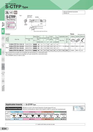
BoringSmal Diameter Turning BarsVery Smal Diameter Turning Holder Material WF Ref. Page Legend SEC-Boring Bar S-CTFP Type 91° Steel Internal General-purposeClamp-on S-CTFP Fig 1 DMIN Min.Bore Dia.DCON Stop Boring 93˚ H GAMF LF 5° LHD E Figure shows right-hand (R) tool. Holder Parts Dimensions (mm) C Cat. No. Previous Cat. No. Stock R L Min. Bore Dia. Diameter Height Overall Length Cutting Edge Distance Head Rake Angle Applicable InsertCat. No. Fig Clamp Double Screw Wrench DMIN DCON H LF WF LHD GAMF (For Hex Socket) S12M-CTFP R/L1103-16 S12M-CTFP R/L 11 ● ● 16 12 11 150 8.0 17 -6° 1 D S16Q-CTFP R/L1103-20 S16Q-CTFP R/L 11 ● ● 20 16 15 180 10.0 18 -4° TP□□1103 B115 on 1 CCM5BSL/R* WB5-10 LH025 Steel S20R-CTFP R/L1103-25 S20R-CTFP R/L 11 ● ● 25 20 18 200 12.5 18 -2° 1 S25S-CTFP R/L1603-32 S25S-CTFP R/L 16 ● ● 32 25 23 250 16.0 38 -2° TP□□1603 B116 1 CCM8UR/L WB8R/L-16T LT27 R Right-handed (R) tool holders are compatible with left-handed (L) or neutral (N) inserts. Left-handed (L) tool holders are compatible with right-handed (R) or neutral (N) inserts. *The CCM5BSR clamp is made to order. S T V W Applicable Inserts S-CTFP Type 1st Recommended Insert ● Refer as well to the Insert Selection Guide (page A10 on).● Some combinations need to be made to order or cannot be manufactured. Name ofChipbreaker/GUCBN/PCDPhotoGradeAC8025P Cutting Range P (Steel) K (Cast Iron) S (Exotic Alloy) N (Non-ferrous) H (Hardened Steel) Process Finishing Medium Cutting High-speed Finishing Finishing to Medium Cutting Medium to Roughing Finishing to Medium Cutting Medium to Roughing — Uncoated General FK SF SUMIBORON No Chipbreaker No Chipbreaker No Chipbreaker No Chipbreaker SUMIDIA SUMIBORON Cutting T1500Z AC8025P BN7000/BN500 AC4015K AC4015K AC5015S AC5025S DA1000 BN2000 RecommendedCutting ConditionsA10 on A16 on A18 on A22 on A20 on 11° inserts with holes can also be used. E54