Общий каталог Lamina Technologies 2019 - 2020 - страница 189
Навигация
 Общий каталог Lamina Technologies 2017 - 2018
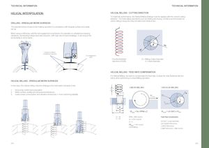
TECHNICAL INFORMATION TECHNICAL INFORMATION HELICAL INTERPOLATION HELICAL MILLING - CUTTING DIRECTION To maximize performance, the Helical Milling strategy must be applied with the correct cutting direction. For holemaking operations such as drilling and boring, CCLW is recommended for climb milling to keep the chip formation from thick to thin. DRILLING - IRREGULAR WORK SURFACES The example below shows a hole-making operation in a workpiece with irregular surface and weak set-up. When using a drill body, until the full engagement is achieved, the operation is unbalanced causing vibrations, demanding a large feed rate reduction, with high risk of insert breakage. It can reduce the productivity in some cases. ØD ØC Irregular surfaces / Unbalanced operation Full engagement area Counterclockwise D = Milling Cutter Diameter direction (CCLW) C = Hole Diameter HELICAL MILLING - FEED RATE COMPENSATION For Helical Milling, we need to compensate the feed rate, to keep the chip thickness like the same when performing a Linear Milling operation. HELICAL MILLING - IRREGULAR WORK SURFACES In this case, the helical milling machine strategy is the best option because it has: LINEAR MILLING CIRCULAR MILLING 1. Good chip control and evacuation P 2. Better surface quality and dimensional tolerances ØD 3. Lower power consumption and vibration tendencies = more machining stability Vflinear ØC Vfcircular D1 D C Vflinear = fz x RPM x Z Vfcircular = ((C-D)/C) x Vflinear D = 16 RPM = 3600 rev/min Feed Rate Compensation C = 30 fz = 0.05 mm/tooth Z=4 ((C-D/C) * Linear feed Rate Vflinear = 720 mm/min ((30-16)/30)*720mm/min(14/30)*720mm/min Climb Milling 0.466*720mm/min = 366 mm/min 374 375