Общий каталог Lamina Technologies 2019 - 2020 - страница 179
Навигация
 Общий каталог Lamina Technologies 2017 - 2018
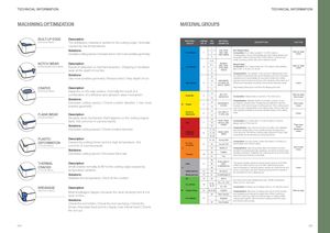
TECHNICAL INFORMATION TECHNICAL INFORMATION MACHINING OPTIMIZATION MATERIAL GROUPS BUILT-UP EDGE Description (Adhesive Wear) The workpiece material is welded to the cutting edge. Normally MATERIAL LAMINA VDI MATERIALGROUPGR. N°GRPEXAMPLES DESCRIPTION CAUTION caused by low temperatures 1 SolutionsIncrease cutting speed / Increase feed / Use more positive geometry Non Alloyed 1 2 C35, Ck45, Non-alloyed Steel1020, 1045,Composition: Fe-C alloy (usually 0.1 to 0.6% carbon).1060, 28Mn6Characteristics: Good machinability and high cutting speeds canBuilt-up edgeCrater 3 be applied. When it has less than 0.25% carbon, it can be very 4, 6 sticky, requiring positive rake and small land inserts. NOTCH WEAR Description(Adhesive/Mechanic Wear)Result of adhesive or mechanical action. Chipping or localizedwear at the depth of cut line. Low AlloyedP 2 5, 76 42CrMo4, Alloyed SteelSt50, Ck60,4140, 4340,100Cr6Composition: Fe-C alloy (maximum 2.1% carbon) with additiveslike Cr, Mo, V, Ni, Mn, Co, W, etc.Built-up edgeCrater SolutionsUse more positive geometry / Reduce feed / Vary depth of cut 8 Characteristics: The variation in the amount of alloying elements10and different heat treatments control features such as mechanicalresistance and machinability. It’s important to follow the cutting 10 X40CrMoV5, speeds recommended according to the hardness of the steel, as it High Alloyed 3 H13, M42, D3, influences temperature as well as chemical and adhesive wears. Crater 11 S6-5-2, 12Ni19 CRATER Description High alloyed Steel have more than 5% alloying elements.11 (Chemical Wear) Happens on the rake surface. Normally the result of a combination of a diffusion and abrasion wear mechanism.Solutions Austenitic 4 14 304, 316,14X5CrNi18-9Composition: Alloyed steel, more than 11% chrome (Cr). Built-up edgeNotch wearCharacteristics: Stainless steels do not stain, corrode, or rust Decrease cutting speed / Check coolant direction / Use morepositive geometry M Duplex 5 14 X2CrNiN23-4, as easily as ordinary steel. Usually they are difficult to machine Notch wear14S31500because of its narrow range of cutting speeds. If the cutting speedCrateris too low, the material sticks in the cutting edge, if it’s too high, the FLANK WEAR Description Ferritic &Martensitic 6 12 high quantity of additives produces abrasive wears in the cutting410, X6Cr17,edge.1317-4PH, 430Crater (Abrasive Wear) Abrasive wear mechanism that happens on the cutting edge’sflank. Not common in Lamina inserts. 15 GG20, GG40, Composition: Fe-C alloy with 2.1 to 5% of carbon. It can beGrey715EN-GJL-250,alloyed with Si, P, Mn and Ni. SolutionsDecrease cutting speed / Check coolant direction. N030B Flank wearKMalleable& Nodular16Characteristics: Grey cast iron tends to be brittle, and malleable17, 19cast irons usually have a more ductile but less homogeneous817, 19GG40, GG70,50005micro-structure. Reinforced cutting edges will perform best. Highproductivity can be achieved by using high feeds.CraterMechanicalcracks 18, 20 PLASTIC DescriptionDEFORMATIONCaused by cutting forces and too high temperature. Not(Thermal Wear)common in Lamina inserts.Solutions 31, 32 Incoloy 800 Composition: Iron (Fe) based, Nickel (Ni) based or Cobalt (Co)Fe, Ni &Co based933Inconel 700based alloys and Titanium alloys.S34Stellite 21Characteristics: High temperature alloys and titanium provideexcellent mechanical strength resistance, as well as corrosion andNotch wearCrater Decrease cutting speed / Decrease feed rate 36 TiAl6V4 oxidation resistance. Relatively low cutting speed is recommendedTi based1037T40due to their poor thermal conductivity. 38 THERMAL Description Steel 11 38 X100 CrMo13,440C, This group includes hardened and tempered steel up to 55 HRc, CRACKS Small cracks normally at 90° to the cutting edge caused by G-X260NiCr42 chilled and white cast iron up to 55 HRc. Machining successH38depends largely on clamping system rigidity, as cutting forces andCrater (Thermal Wear) temperature variation. Chilled Cast Iron 12 40 Ni-Hard 2 power consumption are high. Finishing represents the majority ofthe operations for this material group. Solutions White Cast Iron 13 41 G-X300CrMo15 Stabilize the temperature / Shut off the coolant Alu 14 25 AlSi12 Non-ferrous and soft materials (less than 130HB of hardness). BREAKAGE Description AL (<8%Si) 15 21, 22, 4% < Si < 8% Most common: Aluminium23, 24Si < 4%Composition: Al alloys can be alloyed with Cu, Zn, Mg, Mn and Si. (Mechanic Wear) Most breakages happen because the wear development is notseen in time. NF Copper Alloys 16 26, 27, 28 CuZn30 Characteristics: Aluminium is widely used due to its low density Built-up edge29Fiber Plasticsand relatively good strength to weight ratio. When machining,it tends to have long chips and built-up edge. A highly positive Solutions Non Metallic 17 - Graphite cutting edge together with low friction coating control the chipsand reduce built up edge. Check the tool holder / Check the tool overhang / Check the 30 Hard Rubber Amax / Decrease feed and Vc / Apply more robust insert / Check the run-out 354 355