Основной каталог Kyocera 2016-2017 - страница 951
Навигация
 Каталог Kyocera фрезы MFH для высокоскоростной обработки
 Каталог Kyocera фрезы MEC высокопроизводительные концевые и торцевые фрезы
 Каталог микроинструмента Kyocera 2015-2016
 Каталог Kyocera высокоэффективные сверла со сменными пластинами DRV
 Каталог Kyocera пластины TQ для нарезания резьбы c прессованным стружколомом
 Каталог Kyocera высокопроизводительные модульные сверла DRA
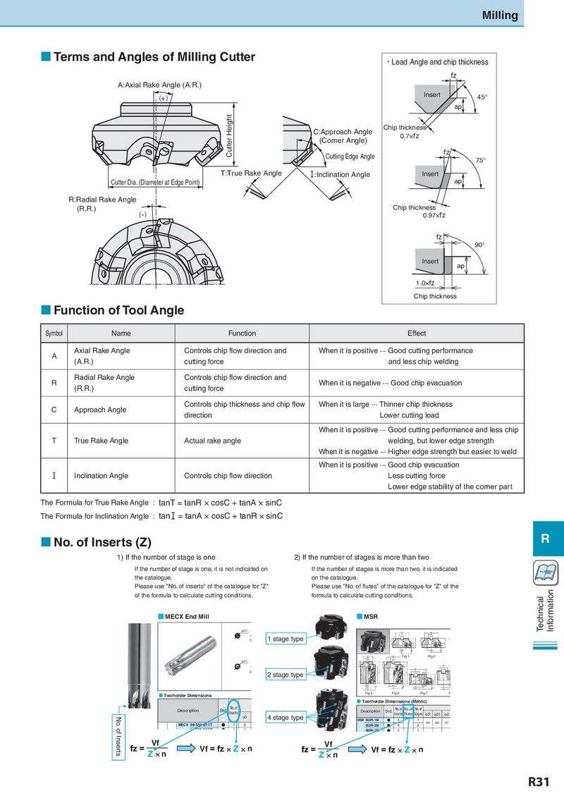
Milling Terms and Angles of Milling Cutter ・Lead Angle and chip thickness fz A:Axial Rake Angle (A.R.) (+) Insert 45° ap Cutter Height C:Approach Angle Chip thickness (Corner Angle) 0.7×fz Cutting Edge Angle fz 75° T:True Rake Angle I :Inclination Angle Insert Cutter Dカia.ッ(Dタia径m(et刃er先at径Ed)ge Point) ap R:Radial Rake Angle (R.R.) Chip thickness (-) 0.97×fz fz 90° Insert ap 1.0×fz Chip thickness Function of Tool Angle Symbol Name Function Effect A Axial Rake Angle Controls chip flow direction and When it is positive ··· Good cutting performance (A.R.) cutting force and less chip welding R Radial Rake Angle Controls chip flow direction and When it is negative ··· Good chip evacuation (R.R.) cutting force C Approach Angle Controls chip thickness and chip flow When it is large ···Thinner chip thickness direction Lower cutting load When it is positive ···Good cutting performance and less chip T True Rake Angle Actual rake angle welding, but lower edge strength When it is negative ··· Higher edge strength but easier to weld When it is positive ···Good chip evacuation I Inclination Angle Controls chip flow direction Less cutting force Lower edge stability of the corner part The Formula for True Rake Angle : tanT = tanR × cosC + tanA × sinC The Formula for Inclination Angle : tan = tanA × cosC + tanR × sinC No. of Inserts (Z) R 1) If the number of stage is one 2) If the number of stages is more than two If the number of stage is one, it is not indicated on If the number of stages is more than two, it is indicated Vc= π×Dm×n the catalogue. on the catalogue. Please use "No. of inserts" of the catalogue for "Z" Please use "No. of flutes" of the catalogue for "Z" of the Information of the formula to calculate cutting conditions. formula to calculate cutting conditions. Technical ■ MECX End Mill ■ MSR qD +0-0.2 qD1 qD1 qd qd b b S 1 stage type a a E E E H H S S qd2 0° qd1 0° qd1 qD qD qD1 qD1 Fig.1 Fig.2 qd qd qD +0 b b -0.2 a a E E qD1 qd qD1 b S qd 2 stage type b qd3 a H H S S E a E G H S qd2 0° qd1 0° qC φd4 qC qd1 qD qD 0° qD qD ● Toolholder Dimensions Fig.5 Fig.6 Fig.7 F ● Toolholder Dimensions (Metric) Description Std. No. of Description Std. No. of No. of No. of Inserts 4 stage type Inserts Flutes Stages φD φD1 φd No. of Inserts φD MSR 063R-1M N 4 1 MECX 08-S10-07-1T N 1 8 063R-2M N 8 4 2 63 50 27 14 S12 07 2T N 2 14 080R-1M N 4 1 Vf Vf n Vf Vf n n n R31