Основной каталог Kyocera 2016-2017 - страница 891
Навигация
 Каталог Kyocera фрезы MFH для высокоскоростной обработки
 Каталог Kyocera фрезы MEC высокопроизводительные концевые и торцевые фрезы
 Каталог микроинструмента Kyocera 2015-2016
 Каталог Kyocera высокоэффективные сверла со сменными пластинами DRV
 Каталог Kyocera пластины TQ для нарезания резьбы c прессованным стружколомом
 Каталог Kyocera высокопроизводительные модульные сверла DRA
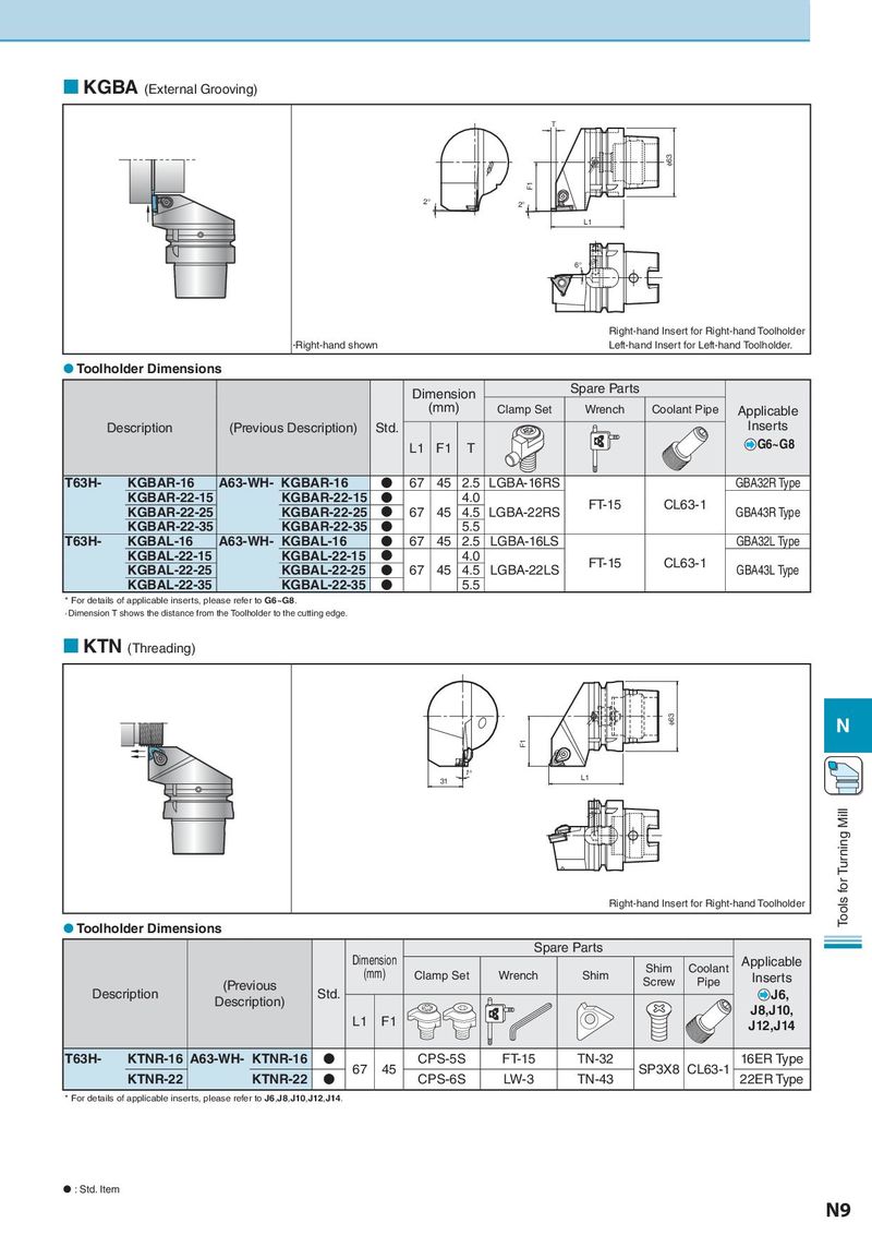
KGBA (External Grooving) T φ63 F1 2° 2° L1 6° Right-hand Insert for Right-hand Toolholder •Right-hand shown Left-hand Insert for Left-hand Toolholder. Toolholder Dimensions Dimension Spare Parts (mm) Clamp Set Wrench Coolant Pipe Applicable Description (Previous Description) Std. Inserts L1 F1 T G6~G8 T63H- KGBAR-16 A63-WH- KGBAR-16 N 67 45 2.5 LGBA-16RS GBA32R Type KGBAR-22-15 KGBAR-22-15 N 4.0 FT-15 CL63-1 KGBAR-22-25 KGBAR-22-25 N 67 45 4.5 LGBA-22RS GBA43R Type KGBAR-22-35 KGBAR-22-35 N 5.5 T63H- KGBAL-16 A63-WH- KGBAL-16 N 67 45 2.5 LGBA-16LS GBA32L Type KGBAL-22-15 KGBAL-22-15 N 4.0 FT-15 CL63-1 KGBAL-22-25 KGBAL-22-25 N 67 45 4.5 LGBA-22LS GBA43L Type KGBAL-22-35 KGBAL-22-35 N 5.5 * For details of applicable inserts, please refer to G6~G8. ·Dimension T shows the distance from the Toolholder to the cutting edge. KTN (Threading) φ63 N F1 1° L1 31 Right-hand Insert for Right-hand Toolholder Tools for Turning Mill Toolholder Dimensions Spare Parts Dimension Shim Coolant Applicable (mm) Clamp Set Wrench Shim Screw Pipe Inserts Description (Previous Std. J6, Description) J8,J10, L1 F1 J12,J14 T63H- KTNR-16 A63-WH- KTNR-16 N 67 45 CPS-5S FT-15 TN-32 SP3X8 CL63-1 16ER Type KTNR-22 KTNR-22 N CPS-6S LW-3 TN-43 22ER Type * For details of applicable inserts, please refer to J6,J8,J10,J12,J14. : Std. Item N9