Основной каталог Kyocera 2016-2017 - страница 872
Навигация
 Каталог Kyocera фрезы MFH для высокоскоростной обработки
 Каталог Kyocera фрезы MEC высокопроизводительные концевые и торцевые фрезы
 Каталог микроинструмента Kyocera 2015-2016
 Каталог Kyocera высокоэффективные сверла со сменными пластинами DRV
 Каталог Kyocera пластины TQ для нарезания резьбы c прессованным стружколомом
 Каталог Kyocera высокопроизводительные модульные сверла DRA
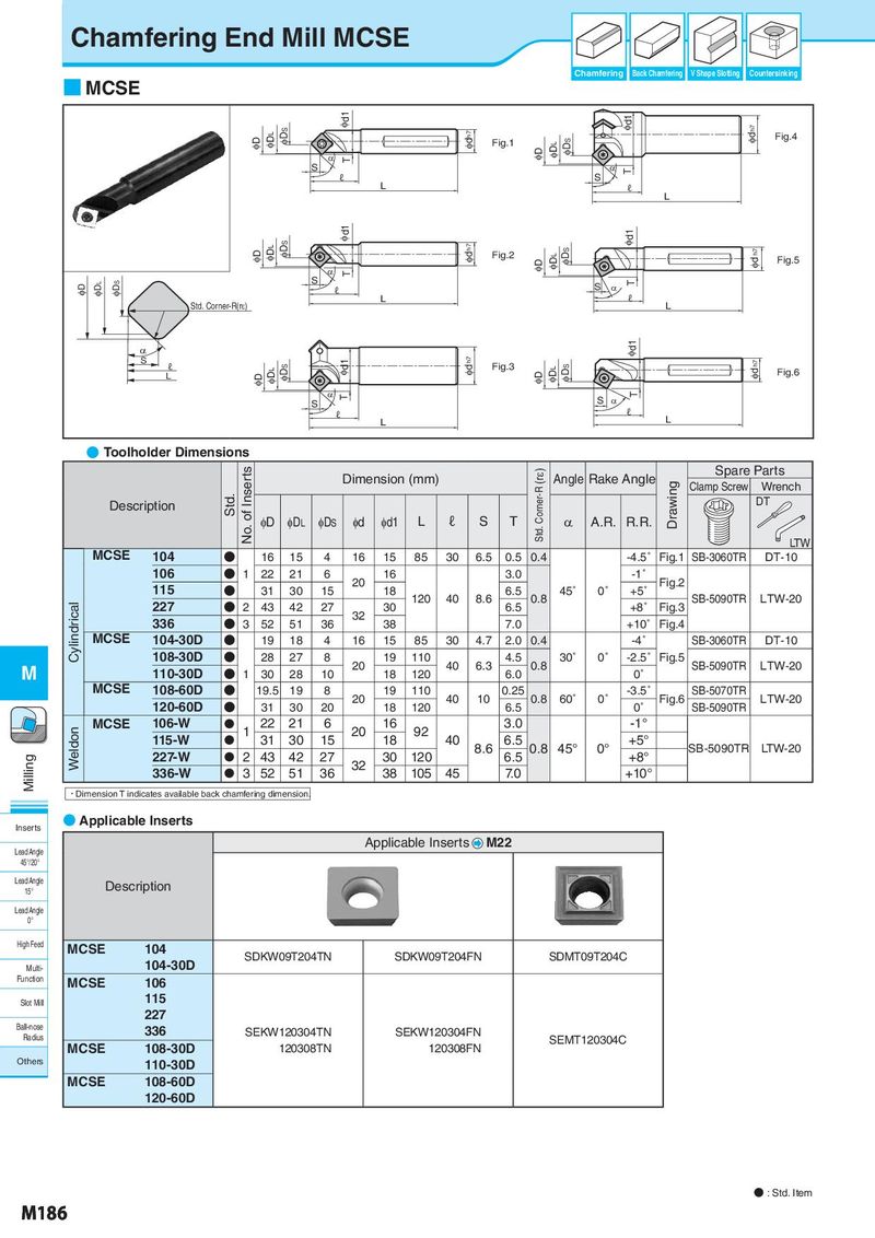
Chamfering End Mill MCSE Chamfering Back Chamfering V Shape Slotting Countersinking ■ MCSE Id1 Id1 Idh7 ID IDL IDS Idh7 Fig.1 IDS Fig.4 D T ID IDL S D T ℓ S L ℓ L IDS Id1 Id1 ID IDL Idh7 Fig.2 ID IDL IDS Id h7 Fig.5 D T ID IDL IDS S S D T ℓ ℓ Std. Corner-R(rH) L L D Id1 S ℓ IDS Id1 Id h7 Fig.3 IDS Id h7 L ID IDL ID IDL Fig.6 D T T S S D ℓ ℓ L L ● Toolholder Dimensions No. of Inserts Dimension (mm) Std. Corner-R (rε) Angle Rake Angle Spare Parts Drawing Clamp Screw Wrench Description Std. DT φD φDL φDS φd φd1 L ℓ S T α A.R. R.R. LTW MCSE 104 ● 16 15 4 16 15 85 30 6.5 0.5 0.4 -4.5˚ Fig.1 SB-3060TR DT-10 106 ● 1 22 21 6 20 16 3.0 -1˚ Fig.2 115 ● 31 30 15 18 120 40 8.6 6.5 0.8 45˚ 0˚ +5˚ SB-5090TR LTW-20 Cylindrical 227 ● 2 43 42 27 32 30 6.5 +8˚ Fig.3 336 ● 3 52 51 36 38 7.0 +10˚ Fig.4 MCSE 104-30D ● 19 18 4 16 15 85 30 4.7 2.0 0.4 -4˚ SB-3060TR DT-10 108-30D ● 28 27 8 20 19 110 40 6.3 4.5 0.8 30˚ 0˚ -2.5˚ Fig.5 SB-5090TR LTW-20 M 110-30D ● 1 30 28 10 18 120 6.0 0˚ MCSE 108-60D ● 19.5 19 8 20 19 110 40 10 0.25 0.8 60˚ 0˚ -3.5˚ Fig.6 SB-5070TR LTW-20 120-60D ● 31 30 20 18 120 6.5 0˚ SB-5090TR Weldon MCSE 106-W N 1 22 21 6 20 16 92 3.0 -1° 115-W N 31 30 15 18 40 8.6 6.5 0.8 45° 0° +5° SB-5090TR LTW-20 Milling 227-W N 2 43 42 27 32 30 120 6.5 +8° 336-W N 3 52 51 36 38 105 45 7.0 +10° ・Dimension T indicates available back chamfering dimension. Inserts ● Applicable Inserts Lead Angle Applicable Inserts M22 45°/20° Lead Angle Description 15° Lead Angle 0° High Feed MCSE 104 104-30D SDKW09T204TN SDKW09T204FN SDMT09T204C Multi- Function MCSE 106 Slot Mill 115 227 Ball-nose 336 SEKW120304TN SEKW120304FN Radius SEMT120304C MCSE 108-30D SEKW120308TN SEKW120308FN Others 110-30D MCSE 108-60D 120-60D ● : Std. Item M186