Основной каталог Kyocera 2016-2017 - страница 817
Навигация
 Каталог Kyocera фрезы MFH для высокоскоростной обработки
 Каталог Kyocera фрезы MEC высокопроизводительные концевые и торцевые фрезы
 Каталог микроинструмента Kyocera 2015-2016
 Каталог Kyocera высокоэффективные сверла со сменными пластинами DRV
 Каталог Kyocera пластины TQ для нарезания резьбы c прессованным стружколомом
 Каталог Kyocera высокопроизводительные модульные сверла DRA
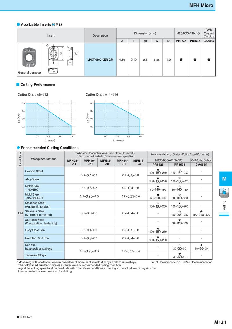
MFH Micro ● Applicable Inserts M13 CVD Insert Description Dimension(mm) MEGACOAT NANO Coated Carbide A T φd W rε PR1535 PR1525 CA6535 rε W φd LPGT 010210ER-GM 4.19 2.19 2.1 6.26 1.0 ● ● ● A T General purpose ■ Cutting Performance Cutter Dia. : φ8~φ12 Cutter Dia. : φ14~φ16 0.5 0.5 0.5 0.5 ap(mm) 0.4 ap(mm) 0.4 ap(mm) 0.4 ap(mm) 0.4 0.3 0.3 0.3 0.3 0.2 0.2 0.2 0.2 0.2 0.2 0.4 0.4 0.6 0.6 0.8 0.8 0.2 0.2 0.4 0.4 0.6 0.6 0.8 0.8 fz(mmf/zt()mm/t) fz(mmf/zt()mm/t) ◆ Recommended Cutting Conditions Insert Type Toolholder Description and Feed Rate(fz [mm/t]) Recommended Insert Grades(Cutting Speed Vc:m/min) * Recommended feed rate (Reference value) : ap=0.3mm Workpiece Material MFH08- MFH10- MFH12- MFH14- MFH16- MEGACOAT NANO CVD Coated Carbide …-1T …-2T …-3T …-3T …-4T PR1525 PR1535 CA6535 Carbon Steel ★ ☆ - 0.2~0.4~0.6 0.2~0.5~0.8 120~180~250 120~180~250 Alloy Steel ★ ☆ - M 100~160~220 100~160~220 Mold Steel 0.2~0.3~0.5 0.2~0.4~0.6 ★ ☆ - (~40HRC) 80~140~180 80~140~180 Mold Steel 0.2~0.25~0.3 0.2~0.25~0.4 ★ ☆ - (40~50HRC) 60~100~130 60~100~130 Stainless Steel ☆ ★ - Milling (Austenitic related) 100~160~200 100~160~200 GM Stainless Steel 0.2~0.3~0.5 0.2~0.4~0.6 - ☆ ★ (Martensitic related) 150~200~250 180~240~300 Stainless Steel - ★ - (Precipitation Hardening) 90~120~150 Gray Cast Iron 0.2~0.4~0.6 0.2~0.5~0.8 ★ - - 120~180~250 Nodular Cast Iron 0.2~0.3~0.5 0.2~0.4~0.6 ★ - - 100~150~200 Ni-base - ☆ ★ heat-resistant alloys 0.2~0.25~0.3 0.2~0.25~0.4 20~30~50 20~30~50 Titanium Alloys - ★ - 40~60~80 * Machining with coolant is recommended for Ni-base heat-resistant alloys and titanium alloys. ★1st Recommendation ☆2nd Recommendation The bold-faced number indicates a center value of recommended cutting condition. Adjust the cutting speed and the feed rate within the above conditions according to the actual machining situation. Internal coolant is recommended for slotting. ● : Std. Item M131