Основной каталог Kyocera 2016-2017 - страница 816
Навигация
 Каталог Kyocera фрезы MFH для высокоскоростной обработки
 Каталог Kyocera фрезы MEC высокопроизводительные концевые и торцевые фрезы
 Каталог микроинструмента Kyocera 2015-2016
 Каталог Kyocera высокоэффективные сверла со сменными пластинами DRV
 Каталог Kyocera пластины TQ для нарезания резьбы c прессованным стружколомом
 Каталог Kyocera высокопроизводительные модульные сверла DRA
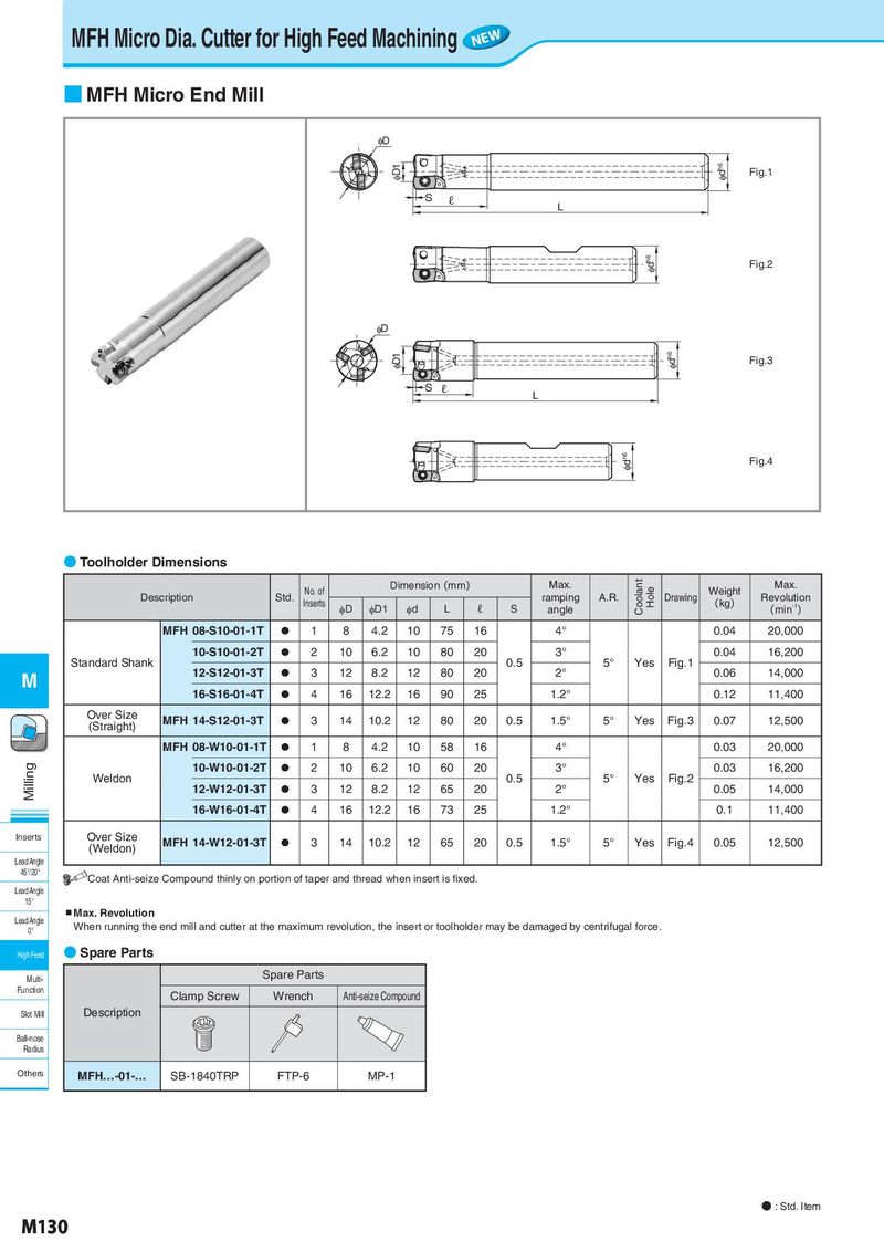
MFH Micro Dia. Cutter for High Feed Machining NEW ■ MFH Micro End Mill φD φD1 φdh6 Fig.1 S ℓ L φdh6 Fig.2 φD φD1 φdh6 Fig.3 S ℓ L φdh6 Fig.4 ● Toolholder Dimensions No. of Dimension(mm) Max. Coolant Hole Weight Max. Description Std. Inserts ramping A.R. Drawing (kg) Revolution φD φD1 φd L ℓ S angle (min-1) MFH 08-S10-01-1T ● 1 8 4.2 10 75 16 4° 0.04 20,000 10-S10-01-2T ● 2 10 6.2 10 80 20 3° 0.04 16,200 Standard Shank 0.5 5° Yes Fig.1 M 12-S12-01-3T ● 3 12 8.2 12 80 20 2° 0.06 14,000 16-S16-01-4T ● 4 16 12.2 16 90 25 1.2° 0.12 11,400 Over Size MFH 14-S12-01-3T ● 3 14 10.2 12 80 20 0.5 1.5° 5° Yes Fig.3 0.07 12,500 (Straight) MFH 08-W10-01-1T ● 1 8 4.2 10 58 16 4° 0.03 20,000 Milling 10-W10-01-2T ● 2 10 6.2 10 60 20 3° 0.03 16,200 Weldon 0.5 5° Yes Fig.2 12-W12-01-3T ● 3 12 8.2 12 65 20 2° 0.05 14,000 16-W16-01-4T ● 4 16 12.2 16 73 25 1.2° 0.1 11,400 Inserts Over Size MFH 14-W12-01-3T ● 3 14 10.2 12 65 20 0.5 1.5° 5° Yes Fig.4 0.05 12,500 (Weldon) Lead Angle 45°/20° Coat Anti-seize Compound thinly on portion of taper and thread when insert is fixed. Lead Angle 15° Lead Angle ▪Max. Revolution 0° When running the end mill and cutter at the maximum revolution, the insert or toolholder may be damaged by centrifugal force. High Feed ● Spare Parts Multi- Spare Parts Function Clamp Screw Wrench Anti-seize Compound Slot Mill Description Ball-nose Radius Others MFH…-01-… SB-1840TRP FTP-6 MP-1 ● : Std. Item M130