Основной каталог Kyocera 2016-2017 - страница 813
Навигация
 Каталог Kyocera фрезы MFH для высокоскоростной обработки
 Каталог Kyocera фрезы MEC высокопроизводительные концевые и торцевые фрезы
 Каталог микроинструмента Kyocera 2015-2016
 Каталог Kyocera высокоэффективные сверла со сменными пластинами DRV
 Каталог Kyocera пластины TQ для нарезания резьбы c прессованным стружколомом
 Каталог Kyocera высокопроизводительные модульные сверла DRA
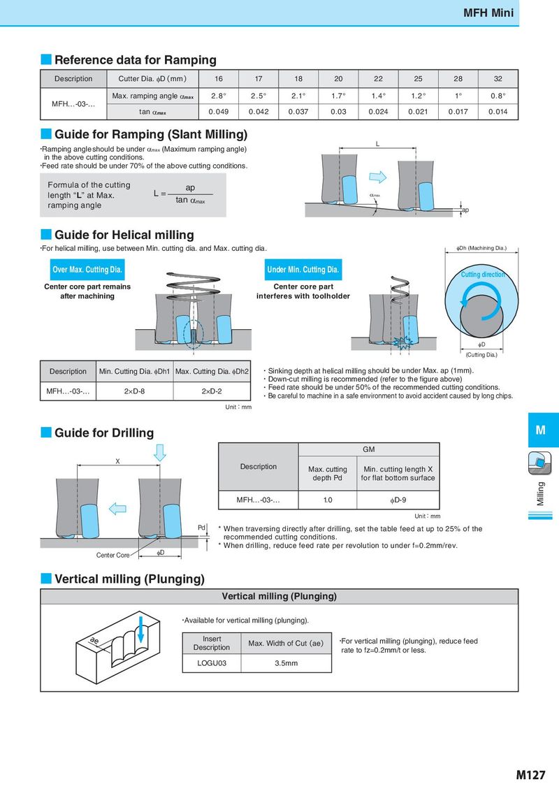
MFH Mini ■ Reference data for Ramping Description Cutter Dia. φD(mm) 16 17 18 20 22 25 28 32 Max. ramping angle αmax 2.8° 2.5° 2 .1° 1.7° 1.4° 1. 2 ° 1° 0.8° MFH…-03-… tan αmax 0.049 0.042 0.037 0.03 0.024 0.021 0 . 017 0 . 014 ■ Guide for Ramping (Slant Milling) ・Ramping angle should be under αmax (Maximum ramping angle) L in the above cutting conditions. ・Feed rate should be under 70% of the above cutting conditions. Formula of the cutting ap length “L” at Max. L= tan αmax αmax ramping angle ap ■ Guide for Helical milling ・For helical milling, use between Min. cutting dia. and Max. cutting dia. qDh (Machining Dia.) Over Max. Cutting Dia. Under Min. Cutting Dia. Cutting direction Center core part remains Center core part after machining interferes with toolholder qD (Cutting Dia.) Description Min. Cutting Dia. φDh1 Max. Cutting Dia. φDh2 ・Sinking depth at helical milling should be under Max. ap (1mm). ・Down-cut milling is recommended (refer to the figure above) MFH…-03-… 2×D-8 2×D-2 ・Feed rate should be under 50% of the recommended cutting conditions. ・Be careful to machine in a safe environment to avoid accident caused by long chips. Unit:mm ■ Guide for Drilling M GM X Description Max. cutting Min. cutting length X depth Pd for flat bottom surface MFH…-03-… 1.0 φD-9 Milling Unit:mm Pd * When traversing directly after drilling, set the table feed at up to 25% of the recommended cutting conditions. * When drilling, reduce feed rate per revolution to under f=0.2mm/rev. Center Core φD ■ Vertical milling (Plunging) Vertical milling (Plunging) ・Available for vertical milling (plunging). Insert Max. Width of Cut(ae) ・For vertical milling (plunging), reduce feed Description rate to fz=0.2mm/t or less. LOGU03 3.5mm M127