Основной каталог Kyocera 2016-2017 - страница 812
Навигация
 Каталог Kyocera фрезы MFH для высокоскоростной обработки
 Каталог Kyocera фрезы MEC высокопроизводительные концевые и торцевые фрезы
 Каталог микроинструмента Kyocera 2015-2016
 Каталог Kyocera высокоэффективные сверла со сменными пластинами DRV
 Каталог Kyocera пластины TQ для нарезания резьбы c прессованным стружколомом
 Каталог Kyocera высокопроизводительные модульные сверла DRA
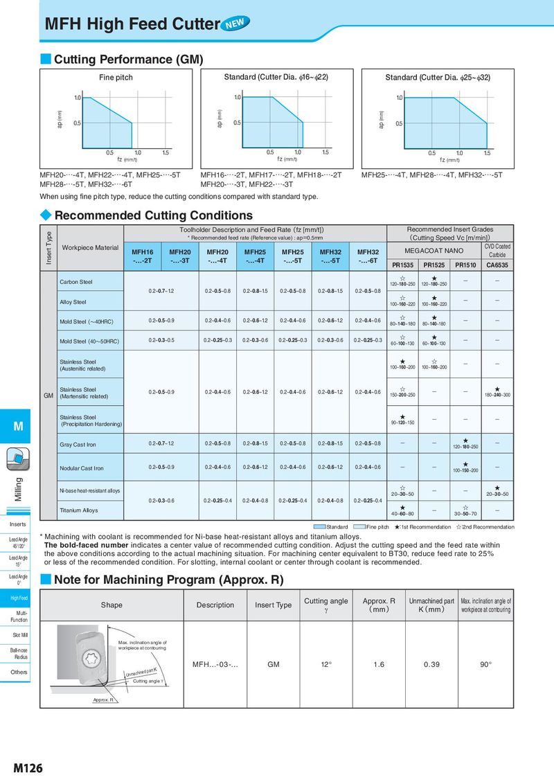
MFH High Feed Cutter NEW ■ Cutting Performance (GM) Fine pitch Standard (Cutter Dia. φ16~φ22) Standard (Cutter Dia. φ25~φ32) 1.0 1.0 1.0 ap (mm) 0.5 ap (mm) 0.5 ap (mm) 0.5 0.5 1.0 1.5 0.5 1.0 1.5 0.5 1.0 1.5 fz (mm/t) fz (mm/t) fz (mm/t) MFH20-…-4T, MFH22-…-4T, MFH25-…-5T MFH16-…-2T, MFH17-…-2T, MFH18-…-2T MFH25-…-4T, MFH28-…-4T, MFH32-…-5T MFH28-…-5T, MFH32-…-6T MFH20-…-3T, MFH22-…-3T When using fine pitch type, reduce the cutting conditions compared with standard type. ◆ Recommended Cutting Conditions Insert Type Toolholder Description and Feed Rate(fz [mm/t]) Recommended Insert Grades * Recommended feed rate (Reference value) : ap=0.5mm (Cutting Speed Vc [m/min]) Workpiece Material MFH16 MFH20 MFH20 MFH25 MFH25 MFH32 MFH32 MEGACOAT NANO CVD Coated -…-2T -…-3T -…-4T -…-4T -…-5T -…-5T -…-6T Carbide PR1535 PR1525 PR1510 CA6535 Carbon Steel ☆ ★ - - 120~180~250 120~180~250 0.2~0.7~1.2 0.2~0.5~0.8 0.2~0.8~1.5 0.2~0.5~0.8 0.2~0.8~1.5 0.2~0.5~0.8 Alloy Steel ☆ ★ - - 100~160~220 100~160~220 Mold Steel(~40HRC) 0.2~0.5~0.9 0.2~0.4~0.6 0.2~0.6~1.2 0.2~0.4~0.6 0.2~0.6~1.2 0.2~0.4~0.6 ☆ ★ - - 80~140~180 80~140~180 Mold Steel(40~50HRC) 0.2~0.3~0.5 0.2~0.25~0.3 0.2~0.3~0.6 0.2~0.25~0.3 0.2~0.3~0.6 0.2~0.25~0.3 ☆ ★ - - 60~100~130 60~100~130 Stainless Steel ★ ☆ - - (Austenitic related) 100~160~200 100~160~200 Stainless Steel 0.2~0.5~0.9 0.2~0.4~0.6 0.2~0.6~1.2 0.2~0.4~0.6 0.2~0.6~1.2 0.2~0.4~0.6 ☆ - - ★ GM (Martensitic related) 150~200~250 180~240~300 Stainless Steel ★ - - - M (Precipitation Hardening) 90~120~150 Gray Cast Iron 0.2~0.7~1.2 0.2~0.5~0.8 0.2~0.8~1.5 0.2~0.5~0.8 0.2~0.8~1.5 0.2~0.5~0.8 - - ★ - 120~180~250 Nodular Cast Iron 0.2~0.5~0.9 0.2~0.4~0.6 0.2~0.6~1.2 0.2~0.4~0.6 0.2~0.6~1.2 0.2~0.4~0.6 - - ★ - 100~150~200 Milling Ni-base heat-resistant alloys ☆ - - ★ 20~30~50 20~30~50 0.2~0.3~0.6 0.2~0.25~0.4 0.2~0.4~0.8 0.2~0.25~0.4 0.2~0.4~0.8 0.2~0.25~0.4 Titanium Alloys ★ - ☆ - 40~60~80 30~50~70 Inserts ■Standard ■Fine pitch ★:1st Recommendation ☆:2nd Recommendation Lead Angle * Machining with coolant is recommended for Ni-base heat-resistant alloys and titanium alloys. 45°/20° The bold-faced number indicates a center value of recommended cutting condition. Adjust the cutting speed and the feed rate within Lead Angle the above conditions according to the actual machining situation. For machining center equivalent to BT30, reduce feed rate to 25% 15° or less of the recommended condition. For slotting, internal coolant or center through coolant is recommended. Lead Angle ■ Note for Machining Program (Approx. R) 0° High Feed Cutting angle Approx. R Unmachined part Max. inclination angle of Shape Description Insert Type γ ( mm ) K( mm ) workpiece at contouring Multi- Function Slot Mill Max. inclination angle of Ball-nose workpiece at contouring Radius Unmachined part K MFH…- 03 -… GM 12° 1.6 0.39 90° Others Cutting angle γ Approx. R M126