Основной каталог Kyocera 2016-2017 - страница 811
Навигация
 Каталог Kyocera фрезы MFH для высокоскоростной обработки
 Каталог Kyocera фрезы MEC высокопроизводительные концевые и торцевые фрезы
 Каталог микроинструмента Kyocera 2015-2016
 Каталог Kyocera высокоэффективные сверла со сменными пластинами DRV
 Каталог Kyocera пластины TQ для нарезания резьбы c прессованным стружколомом
 Каталог Kyocera высокопроизводительные модульные сверла DRA
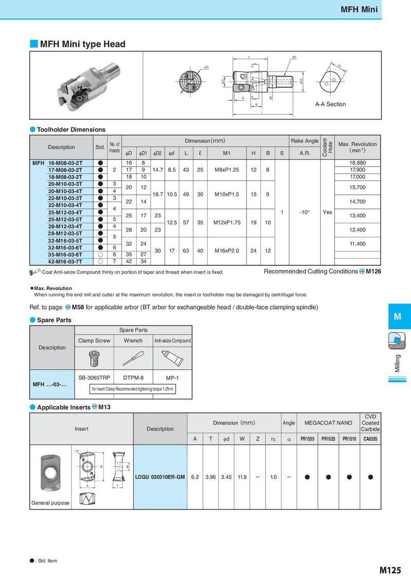
MFH Mini ■ MFH Mini type Head ℓ M1 φD A H φD1 φD2 S A φd B A-A Section L ● Toolholder Dimensions No. of Dimension(mm) Rake Angle Coolant Hole Max. Revolution Description Std. Inserts (min-1) φD φD1 φD2 φd L ℓ M1 H B S A.R. MFH 16-M08-03-2T ● 16 8 18,880 17-M08-03-2T ● 2 17 9 14.7 8.5 43 25 M8xP1.25 12 8 17,900 18-M08-03-2T ● 18 10 17,000 20-M10-03-3T ● 3 20 12 15,700 20-M10-03-4T ● 4 18.7 10.5 49 30 M10xP1.5 15 9 22-M10-03-3T ● 3 22 14 14,700 22-M10-03-4T ● 4 25-M12-03-4T ● 25 17 23 1 -10° Yes 13,400 25-M12-03-5T ● 5 12.5 57 35 M12xP1.75 19 10 28-M12-03-4T ● 4 28 20 23 12,400 28-M12-03-5T ● 5 32-M16-03-5T ● 32 24 11,400 32-M16-03-6T ● 6 30 17 63 40 M16xP2.0 24 12 35-M16-03-6T ○ 6 35 27 42-M16-03-7T ○ 7 42 34 Coat Anti-seize Compound thinly on portion of taper and thread when insert is fixed. Recommended Cutting Conditions M126 ▪Max. Revolution When running the end mill and cutter at the maximum revolution, the insert or toolholder may be damaged by centrifugal force. Ref. to page M58 for applicable arbor (BT arbor for exchangeable head / double-face clamping spindle) ● Spare Parts M Spare Parts Clamp Screw Wrench Anti-seize Compound Description Milling SB-3065TRP DTPM-8 MP-1 MFH …-03-… for Insert Clamp Recommended tightening torque 1.2N・m ● Applicable Inserts M13 CVD Dimension(mm) Angle MEGACOAT NANO Coated Insert Description Carbide A T φd W Z rε α PR1535 PR1525 PR1510 CA6535 rε W φd LOGU 030310ER-GM 6.2 3.96 3.45 11.9 - 1.0 - ● ● ● ● A T General purpose ● : Std. Item M125