Основной каталог Kyocera 2016-2017 - страница 810
Навигация
 Каталог Kyocera фрезы MFH для высокоскоростной обработки
 Каталог Kyocera фрезы MEC высокопроизводительные концевые и торцевые фрезы
 Каталог микроинструмента Kyocera 2015-2016
 Каталог Kyocera высокоэффективные сверла со сменными пластинами DRV
 Каталог Kyocera пластины TQ для нарезания резьбы c прессованным стружколомом
 Каталог Kyocera высокопроизводительные модульные сверла DRA
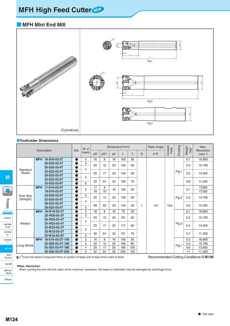
MFH High Feed Cutter NEW ■ MFH Mini End Mill φD φ D1 φdh6 S ℓ L Fig.1 φ D φD1 φdh6 S ℓ L Fig.2 φdh6 Fig.3 (Cylindrical) ●Toolholder Dimensions No. of Dimension(mm) Rake Angle Coolant Hole Drawing Weight ) Max. Description Std. Inserts kg Revolution φD φD1 φd L ℓ S A.R. ( (min-1) MFH 16-S16-03-2T ● 2 16 8 16 100 30 0.1 18,800 20-S20-03-3T ● 3 20 12 20 130 50 0.3 15,700 Standard 20-S20-03-4T ● 4 Shank 25-S25-03-4T ● 25 17 25 140 60 Fig.1 0.5 13,400 M 25-S25-03-5T ● 5 32-S32-03-5T ● 32 24 32 150 70 0.8 11,400 32-S32-03-6T ● 6 MFH 17-S16-03-2T ● 2 17 9 16 100 20 0.1 17,900 18-S16-03-2T ● 18 10 17,000 Over Size 22-S20-03-3T ● 3 22 14 20 130 30 Fig.2 0.3 14,700 Milling (Straight) 22-S20-03-4T ● 4 28-S25-03-4T ● 28 20 25 140 40 1 -10° Yes 0.5 12,400 28-S25-03-5T ● 5 MFH 16-W16-03-2T ● 2 16 8 16 79 30 0.1 18,800 20-W20-03-3T ● 3 20 12 20 101 50 0.2 15,700 Inserts 20-W20-03-4T ● Weldon 25-W25-03-4T ● 4 Fig.3 Lead Angle 25 17 25 117 60 0.4 13,400 45°/20° 25-W25-03-5T ● 32-W32-03-5T ● 5 Lead Angle 32 24 32 131 70 0.7 11,400 15° 32-W32-03-6T ● 6 Lead Angle MFH 16-S16-03-2T-150 ● 2 16 8 16 150 50 0.2 18,800 0° 20-S20-03-3T-160 ● 3 20 12 20 160 80 0.3 15,700 Long Shank 25-S25-03-4T-180 ● 4 25 17 25 180 100 Fig.1 0.6 13,400 High Feed 32-S32-03-5T-200 ● 5 32 24 32 200 120 1.1 11,400 Multi- Coat Anti-seize Compound thinly on portion of taper and thread when insert is fixed. Recommended Cutting Conditions M126 Function Slot Mill ▪Max. Revolution Ball-nose When running the end mill and cutter at the maximum revolution, the insert or toolholder may be damaged by centrifugal force. Radius Others ● : Std. Item M124