Основной каталог Kyocera 2016-2017 - страница 778
Навигация
 Каталог Kyocera фрезы MFH для высокоскоростной обработки
 Каталог Kyocera фрезы MEC высокопроизводительные концевые и торцевые фрезы
 Каталог микроинструмента Kyocera 2015-2016
 Каталог Kyocera высокоэффективные сверла со сменными пластинами DRV
 Каталог Kyocera пластины TQ для нарезания резьбы c прессованным стружколомом
 Каталог Kyocera высокопроизводительные модульные сверла DRA
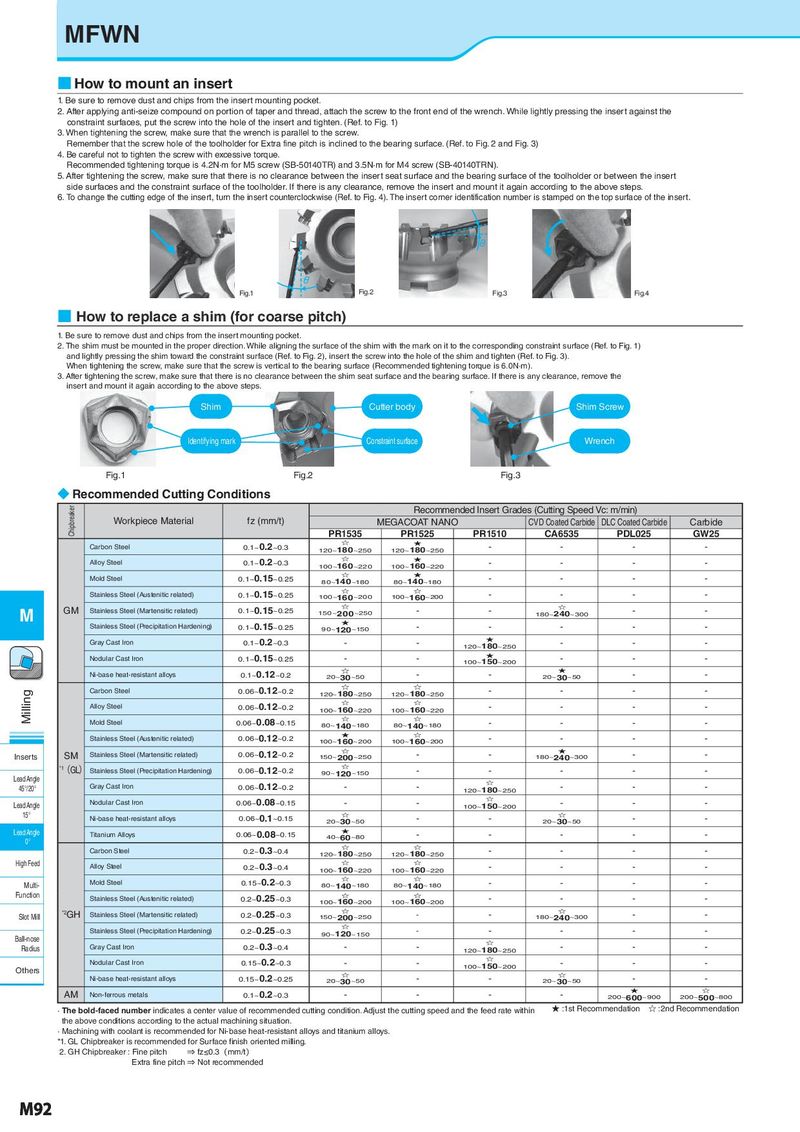
MFWN ■ How to mount an insert 1. Be sure to remove dust and chips from the insert mounting pocket. 2. After applying anti-seize compound on portion of taper and thread, attach the screw to the front end of the wrench. While lightly pressing the insert against the constraint surfaces, put the screw into the hole of the insert and tighten. (Ref. to Fig. 1) 3. When tightening the screw, make sure that the wrench is parallel to the screw. Remember that the screw hole of the toolholder for Extra fine pitch is inclined to the bearing surface. (Ref. to Fig. 2 and Fig. 3) 4. Be careful not to tighten the screw with excessive torque. Recommended tightening torque is 4.2N·m for M5 screw (SB-50140TR) and 3.5N·m for M4 screw (SB-40140TRN). 5. After tightening the screw, make sure that there is no clearance between the insert seat surface and the bearing surface of the toolholder or between the insert side surfaces and the constraint surface of the toolholder. If there is any clearance, remove the insert and mount it again according to the above steps. 6. To change the cutting edge of the insert, turn the insert counterclockwise (Ref. to Fig. 4). The insert corner identification number is stamped on the top surface of the insert. θ θ Fig.1 Fig.2 Fig.3 Fig.4 ■ How to replace a shim (for coarse pitch) 1. Be sure to remove dust and chips from the insert mounting pocket. 2. The shim must be mounted in the proper direction. While aligning the surface of the shim with the mark on it to the corresponding constraint surface (Ref. to Fig. 1) and lightly pressing the shim toward the constraint surface (Ref. to Fig. 2), insert the screw into the hole of the shim and tighten (Ref. to Fig. 3). When tightening the screw, make sure that the screw is vertical to the bearing surface (Recommended tightening torque is 6.0N·m). 3. After tightening the screw, make sure that there is no clearance between the shim seat surface and the bearing surface. If there is any clearance, remove the insert and mount it again according to the above steps. Shim Cutter body Shim Screw Identifying mark Constraint surface Wrench Fig.1 Fig.2 Fig.3 ◆ Recommended Cutting Conditions Chipbreaker Recommended Insert Grades (Cutting Speed Vc: m/min) Workpiece Material fz (mm/t) MEGACOAT NANO CVD Coated Carbide DLC Coated Carbide Carbide PR1535 PR1525 PR1510 CA6535 PDL025 GW25 Carbon Steel 0.1~0.2~0.3 ☆ ★ - - - - 120~180~250 120~180~250 Alloy Steel 0.1~0.2~0.3 ☆ ★ - - - - 100~160~220 100~160~220 Mold Steel 0.1~0.15~0.25 ☆ ★ - - - - 80~140~180 80~140~180 Stainless Steel (Austenitic related) 0.1~0.15~0.25 ☆ ☆ - - - - 100~160~200 100~160~200 M GM Stainless Steel (Martensitic related) 0.1~0.15~0.25 ☆ - - ☆ - - 150 ~ 2 0 0 ~250 180~240~300 Stainless Steel (Precipitation Hardening) 0.1~0.15~0.25 ★ - - - - - 90~120~150 Gray Cast Iron 0.1~0.2~0.3 - - ★ - - - 120~180~250 Nodular Cast Iron 0.1~0.15~0.25 - - ★ - - - 100~150~200 Ni-base heat-resistant alloys 0.1~0.12~0.2 ☆ - - ★ - - 20~30~50 20~30~50 Milling Carbon Steel 0.06~0.12~0.2 ☆ ☆ - - - - 120~180~250 120~180~250 Alloy Steel 0.06~0.12~0.2 ☆ ☆ - - - - 100~160~220 100~160~220 Mold Steel 0.06~0.08~0.15 ☆ ☆ - - - - 80~140~180 80~140~180 Stainless Steel (Austenitic related) 0.06~0.12~0.2 ★ ☆ - - - - 100~160~200 100~160~200 SM Stainless Steel (Martensitic related) 0.06~0.12~0.2 ☆ - - ★ - - Inserts 150~200~250 180~240~300 *1(GL) Stainless Steel (Precipitation Hardening) 0.06~0.12~0.2 ☆ - - - - - Lead Angle 90~120~150 45°/20° Gray Cast Iron 0.06~0.12~0.2 - - ☆ - - - 120~180~250 Nodular Cast Iron 0.06~0.08~0.15 - - ☆ - - - Lead Angle 100~150~200 15° Ni-base heat-resistant alloys 0.06~0.1~0.15 ☆ - - ☆ - - 20~30~50 20~30~50 Lead Angle Titanium Alloys 0.06~0.08~0.15 ★ - - - - - 0° 40~60~80 Carbon Steel 0.2~0.3~0.4 ☆ ☆ - - - - 120~180~250 120~180~250 High Feed Alloy Steel 0.2~0.3~0.4 ☆ ☆ - - - - 100~160~220 100~160~220 Mold Steel 0.15~0.2~0.3 ☆ ☆ - - - - Multi- 80~140~180 80~140~180 Function Stainless Steel (Austenitic related) 0.2~0.25~0.3 ☆ ☆ - - - - 100~160~200 100~160~200 *2GH Stainless Steel (Martensitic related) 0.2~0.25~0.3 ☆ - - ☆ - - Slot Mill 150~200~250 180~240~300 Stainless Steel (Precipitation Hardening) 0.2~0.25~0.3 ☆ - - - - - Ball-nose 90~120~150 Radius Gray Cast Iron 0.2~0.3~0.4 - - ☆ - - - 120~180~250 Nodular Cast Iron 0.15~0.2~0.3 - - ☆ - - - Others 100~150~200 Ni-base heat-resistant alloys 0.15~0.2~0.25 ☆ - - ☆ - - 20~30~50 20~30~50 AM Non-ferrous metals 0.1~0.2~0.3 - - - - ★ ☆ 200~600~900 200~500~800 · The bold-faced number indicates a center value of recommended cutting condition. Adjust the cutting speed and the feed rate within ★ :1st Recommendation ☆ :2nd Recommendation the above conditions according to the actual machining situation. · Machining with coolant is recommended for Ni-base heat-resistant alloys and titanium alloys. *1. GL Chipbreaker is recommended for Surface finish oriented milling. 2. GH Chipbreaker : Fine pitch ⇒ fz≤0.3(mm/t) Extra fine pitch ⇒ Not recommended M92