Основной каталог Kyocera 2016-2017 - страница 649
Навигация
 Каталог Kyocera фрезы MFH для высокоскоростной обработки
 Каталог Kyocera фрезы MEC высокопроизводительные концевые и торцевые фрезы
 Каталог микроинструмента Kyocera 2015-2016
 Каталог Kyocera высокоэффективные сверла со сменными пластинами DRV
 Каталог Kyocera пластины TQ для нарезания резьбы c прессованным стружколомом
 Каталог Kyocera высокопроизводительные модульные сверла DRA
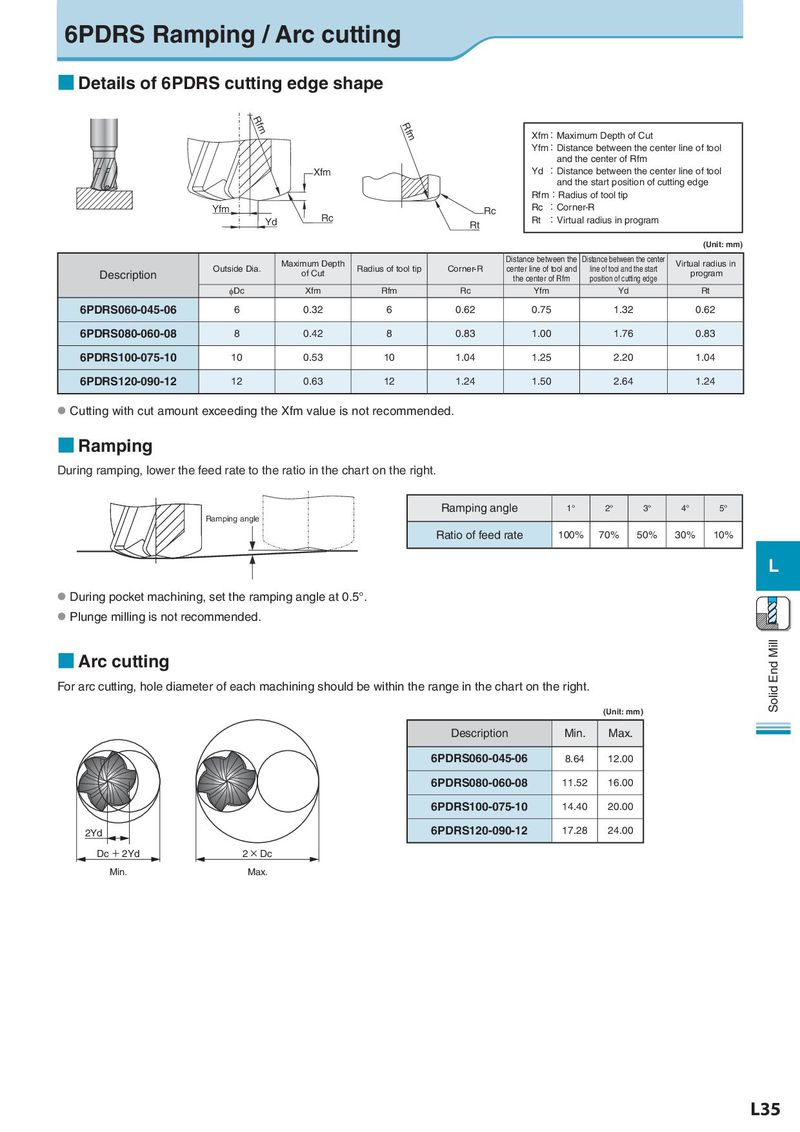
6PDRS Ramping / Arc cutting ■ Details of 6PDRS cutting edge shape Rfm Rfm Xfm:Maximum Depth of Cut Yfm:Distance between the center line of tool and the center of Rfm Xfm Yd :Distance between the center line of tool and the start position of cutting edge Rfm:Radius of tool tip Yfm Rc Rc :Corner-R Yd Rc Rt Rt :Virtual radius in program (Unit: mm) Maximum Depth Distance between the Distance between the center Virtual radius in Description Outside Dia. of Cut Radius of tool tip Corner-R center line of tool and line of tool and the start program the center of Rfm position of cutting edge φDc Xfm Rfm Rc Yfm Yd Rt 6PDRS060-045-06 6 0.32 6 0.62 0.75 1.32 0.62 6PDRS080-060-08 8 0.42 8 0.83 1.00 1.76 0.83 6PDRS100-075-10 10 0.53 10 1.04 1.25 2.20 1.04 6PDRS120-090-12 12 0.63 12 1.24 1.50 2.64 1.24 ● Cutting with cut amount exceeding the Xfm value is not recommended. ■ Ramping During ramping, lower the feed rate to the ratio in the chart on the right. Ramping angle 1° 2° 3° 4° 5° Ramping angle Ratio of feed rate 100% 70% 50% 30% 10% L ● During pocket machining, set the ramping angle at 0.5°. ● Plunge milling is not recommended. ■ Arc cutting Solid End Mill For arc cutting, hole diameter of each machining should be within the range in the chart on the right. (Unit: mm) Description Min. Max. 6PDRS060-045-06 8.64 12.00 6PDRS080-060-08 11.52 16.00 6PDRS100-075-10 14.40 20.00 2Yd 6PDRS120-090-12 17.28 24.00 Dc + 2Yd 2 × Dc Min. Max. L35