Основной каталог Kyocera 2016-2017 - страница 611
Навигация
 Каталог Kyocera фрезы MFH для высокоскоростной обработки
 Каталог Kyocera фрезы MEC высокопроизводительные концевые и торцевые фрезы
 Каталог микроинструмента Kyocera 2015-2016
 Каталог Kyocera высокоэффективные сверла со сменными пластинами DRV
 Каталог Kyocera пластины TQ для нарезания резьбы c прессованным стружколомом
 Каталог Kyocera высокопроизводительные модульные сверла DRA
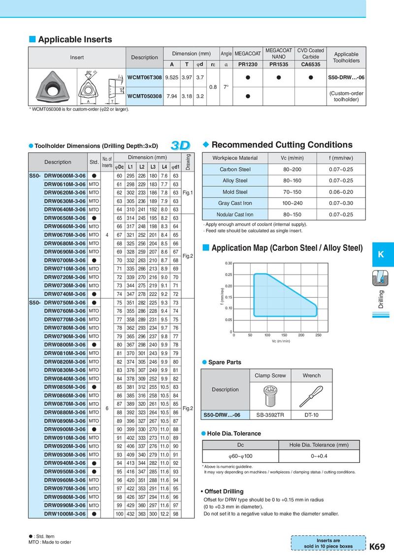
Applicable Inserts Dimension (mm) Angle MEGACOAT MEGACOAT CVD Coated Applicable Insert Description NANO Carbide Toolholders A T φd rε α PR1230 PR1535 CA6535 80° rε 7° WCMT06T308 9.525 3.97 3.7 ● ● ● S50-DRW…-06 φd 0.8 7° WCMT050308 7.94 3.18 3.2 ● (Custom-order A T toolholder) * WCMT050308 is for custom-order (φ22 or larger). Toolholder Dimensions (Drilling Depth:3×D) 3D Recommended Cutting Conditions Description Std. No. of Dimension (mm) Drawing Workpiece Material Vc (m/min) f (mm/rev) Inserts φDc L1 L2 L3 L4 φd1 Carbon Steel 80~200 0.07~0.25 S50- DRW0600M-3-06 ● 60 295 226 180 7.6 63 DRW0610M-3-06 MTO 61 298 229 183 7.7 63 Alloy Steel 80~160 0.07~0.25 DRW0620M-3-06 MTO 62 302 233 186 7.8 63 Fig.1 Mold Steel 70~150 0.06~0.20 DRW0630M-3-06 MTO 63 305 236 189 7.9 63 Gray Cast Iron 100~240 0.07~0.30 DRW0640M-3-06 MTO 64 310 241 192 8.0 63 DRW0650M-3-06 ● 65 314 245 195 8.2 63 Nodular Cast Iron 80~150 0.07~0.25 DRW0660M-3-06 MTO 66 317 248 198 8.3 64 · Apply enough amount of coolant (internal supply). DRW0670M-3-06 4 67 321 252 201 8.4 65 · Feed rate should be calculated as single insert. MTO DRW0680M-3-06 MTO 68 325 256 204 8.5 66 Application Map (Carbon Steel / Alloy Steel) DRW0690M-3-06 MTO 69 328 259 207 8.6 67 Fig.2 K DRW0700M-3-06 ● 70 332 263 210 8.7 68 0.30 DRW0710M-3-06 MTO 71 335 266 213 8.9 69 DRW0720M-3-06 MTO 72 339 270 216 9.0 70 0.25 DRW0730M-3-06 MTO 73 344 275 219 9.1 71 0.20 DRW0740M-3-06 ● 74 347 278 222 9.2 72 f (mm/rev) 0.15 Drilling S50- DRW0750M-3-06 ● 75 351 282 225 9.3 73 DRW0760M-3-06 MTO 76 355 286 228 9.4 74 0.10 DRW0770M-3-06 MTO 77 358 289 231 9.5 75 0.05 DRW0780M-3-06 MTO 78 362 293 234 9.7 76 0 0 50 100 150 200 250 DRW0790M-3-06 MTO 79 365 296 237 9.8 77 Vc (m/min) DRW0800M-3-06 ● 80 367 298 240 9.9 78 DRW0810M-3-06 MTO 81 370 301 243 9.9 79 DRW0820M-3-06 MTO 82 374 305 246 9.9 80 Spare Parts DRW0830M-3-06 MTO 83 376 307 249 9.9 81 DRW0840M-3-06 MTO 84 378 309 252 9.9 82 Clamp Screw Wrench DRW0850M-3-06 ● 85 381 312 255 10.5 83 Description DRW0860M-3-06 MTO 86 385 316 258 10.5 84 DRW0870M-3-06 MTO 6 87 389 320 261 10.5 85 Fig.2 DRW0880M-3-06 MTO 88 392 323 264 10.5 86 S50-DRW…-06 SB-3592TR DT-10 DRW0890M-3-06 MTO 89 396 327 267 10.5 87 DRW0900M-3-06 ● 90 399 330 270 11.0 88 Hole Dia. Tolerance DRW0910M-3-06 MTO 91 402 333 273 11.0 89 DRW0920M-3-06 MTO 92 406 337 276 11.0 90 Dc Hole Dia. Tolerance (mm) DRW0930M-3-06 MTO 93 409 340 279 11.0 91 φ60~φ100 0~+0.4 DRW0940M-3-06 ● 94 413 344 282 11.0 92 * Above is numeric guideline. DRW0950M-3-06 ● 95 416 347 285 11.6 93 It may vary depending on machines / workpieces / clamping status / cutting conditions. DRW0960M-3-06 MTO 96 420 351 288 11.6 94 DRW0970M-3-06 MTO 97 422 353 291 11.6 95 • Offset Drilling DRW0980M-3-06 MTO 98 426 357 294 11.6 96 Offset for DRW type should be 0 to +0.15 mm in radius DRW0990M-3-06 MTO 99 429 360 297 11.6 97 (0 to +0.3 mm in diameter). DRW1000M-3-06 ● 100 432 363 300 12.2 98 Do not set it to a negative value to make the diameter smaller. : Std. Item MTO : Made to order Inserts are sold in 10 piece boxes K69