Основной каталог Kyocera 2016-2017 - страница 592
Навигация
 Каталог Kyocera фрезы MFH для высокоскоростной обработки
 Каталог Kyocera фрезы MEC высокопроизводительные концевые и торцевые фрезы
 Каталог микроинструмента Kyocera 2015-2016
 Каталог Kyocera высокоэффективные сверла со сменными пластинами DRV
 Каталог Kyocera пластины TQ для нарезания резьбы c прессованным стружколомом
 Каталог Kyocera высокопроизводительные модульные сверла DRA
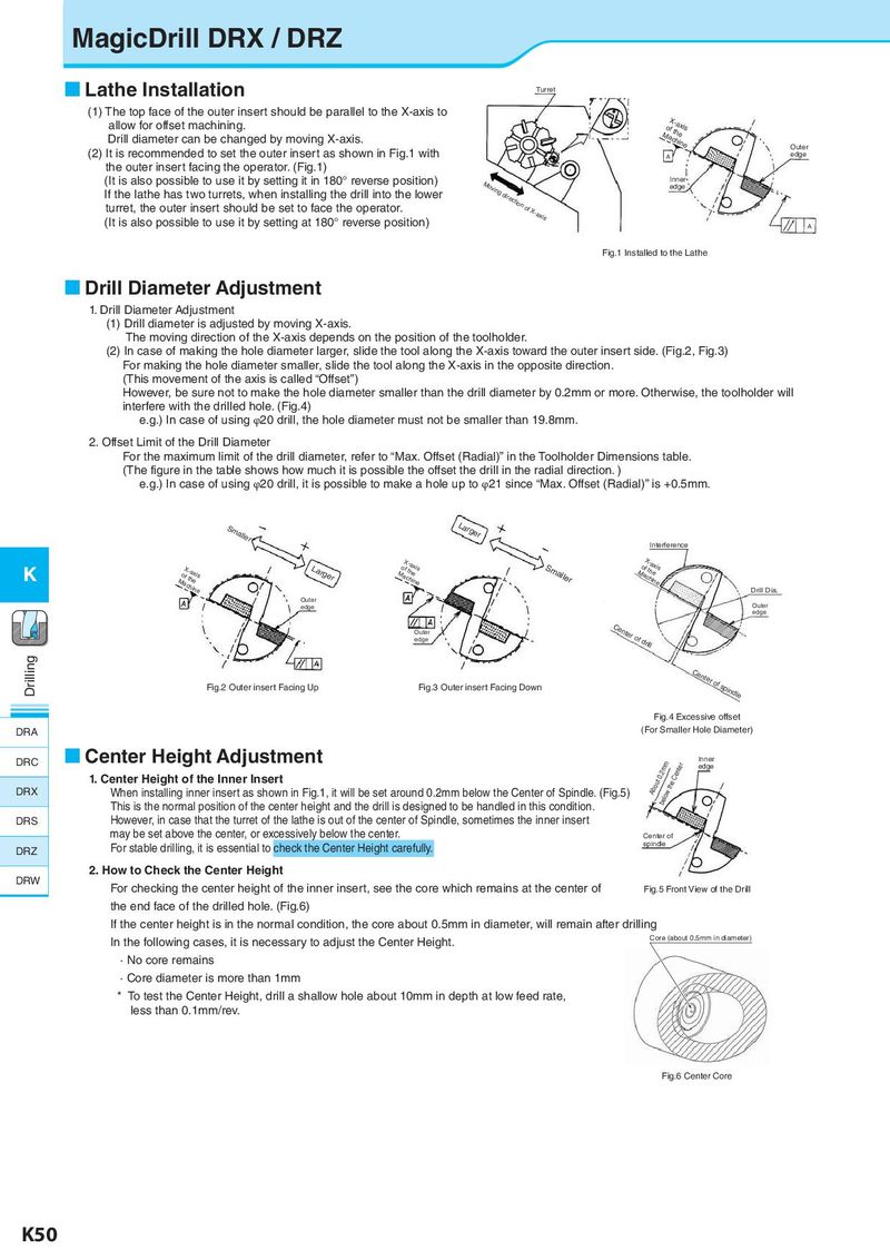
MagicDrill DRX / DRZ Lathe Installation Turret (1) The top face of the outer insert should be parallel to the X-axis to MoaXfct-hhaiexnies allow for offset machining. Drill diameter can be changed by moving X-axis. Outer (2) It is recommended to set the outer insert as shown in Fig.1 with A edge the outer insert facing the operator. (Fig.1) (It is also possible to use it by setting it in 180° reverse position) Moving direction of X-axis Inner If the lathe has two turrets, when installing the drill into the lower edge turret, the outer insert should be set to face the operator. (It is also possible to use it by setting at 180° reverse position) A (図1)Fi旋g.盤1 へInsのta取lle付dけto状th態e Lathe Drill Diameter Adjustment 1. Drill Diameter Adjustment (1) Drill diameter is adjusted by moving X-axis. The moving direction of the X-axis depends on the position of the toolholder. (2) In case of making the hole diameter larger, slide the tool along the X-axis toward the outer insert side. (Fig.2, Fig.3) For making the hole diameter smaller, slide the tool along the X-axis in the opposite direction. (This movement of the axis is called “Offset”) However, be sure not to make the hole diameter smaller than the drill diameter by 0.2mm or more. Otherwise, the toolholder will interfere with the drilled hole. (Fig.4) e.g.) In case of using φ20 drill, the hole diameter must not be smaller than 19.8mm. 2. Offset Limit of the Drill Diameter For the maximum limit of the drill diameter, refer to “Max. Offset (Radial)” in the Toolholder Dimensions table. (The figure in the table shows how much it is possible the offset the drill in the radial direction. ) e.g.) In case of using φ20 drill, it is possible to make a hole up to φ21 since “Max. Offset (Radial)” is +0.5mm. Smaller Larger Interference K MoaXfct-hhaiexnies Larger MoaXfct-hhaiexnies Smaller MoafXcth-haienxeis Drill Dia. Outer edge Outer edge Outer Center of drill edge Drilling (図2)外刃上面が上向きの状態 F(ig図.33O)u外te刃r i上ns面erがt F下a向cinきgのD状ow態n Center of spindle Fig.2 Outer insert Facing Up (図Fi4g).4穴E径xがce小sさsiすveぎoるffs場e合t DRA (For Smaller Hole Diameter) DRC Center Height Adjustment Inner beloAwbtohuetC0.e2ntmerm edge 1. Center Height of the Inner Insert DRX When installing inner insert as shown in Fig.1, it will be set around 0.2mm below the Center of Spindle. (Fig.5) This is the normal position of the center height and the drill is designed to be handled in this condition. DRS However, in case that the turret of the lathe is out of the center of Spindle, sometimes the inner insert may be set above the center, or excessively below the center. Center of DRZ For stable drilling, it is essential to check the Center Height carefully. spindle 2. How to Check the Center Height DRW For checking the center height of the inner insert, see the core which remains at the center of Fi(g.図5 5F)roドntリViルew正o面f 図the Drill the end face of the drilled hole. (Fig.6) If the center height is in the normal condition, the core about 0.5mm in diameter, will remain after drilling In the following cases, it is necessary to adjust the Center Height. Core (about 0.5mm in diameter) · No core remains · Core diameter is more than 1mm * To test the Center Height, drill a shallow hole about 10mm in depth at low feed rate, less than 0.1mm/rev. F(ig図.66C)e中nt心er部Cコorアe K50