Основной каталог Kyocera 2016-2017 - страница 591
Навигация
 Каталог Kyocera фрезы MFH для высокоскоростной обработки
 Каталог Kyocera фрезы MEC высокопроизводительные концевые и торцевые фрезы
 Каталог микроинструмента Kyocera 2015-2016
 Каталог Kyocera высокоэффективные сверла со сменными пластинами DRV
 Каталог Kyocera пластины TQ для нарезания резьбы c прессованным стружколомом
 Каталог Kyocera высокопроизводительные модульные сверла DRA
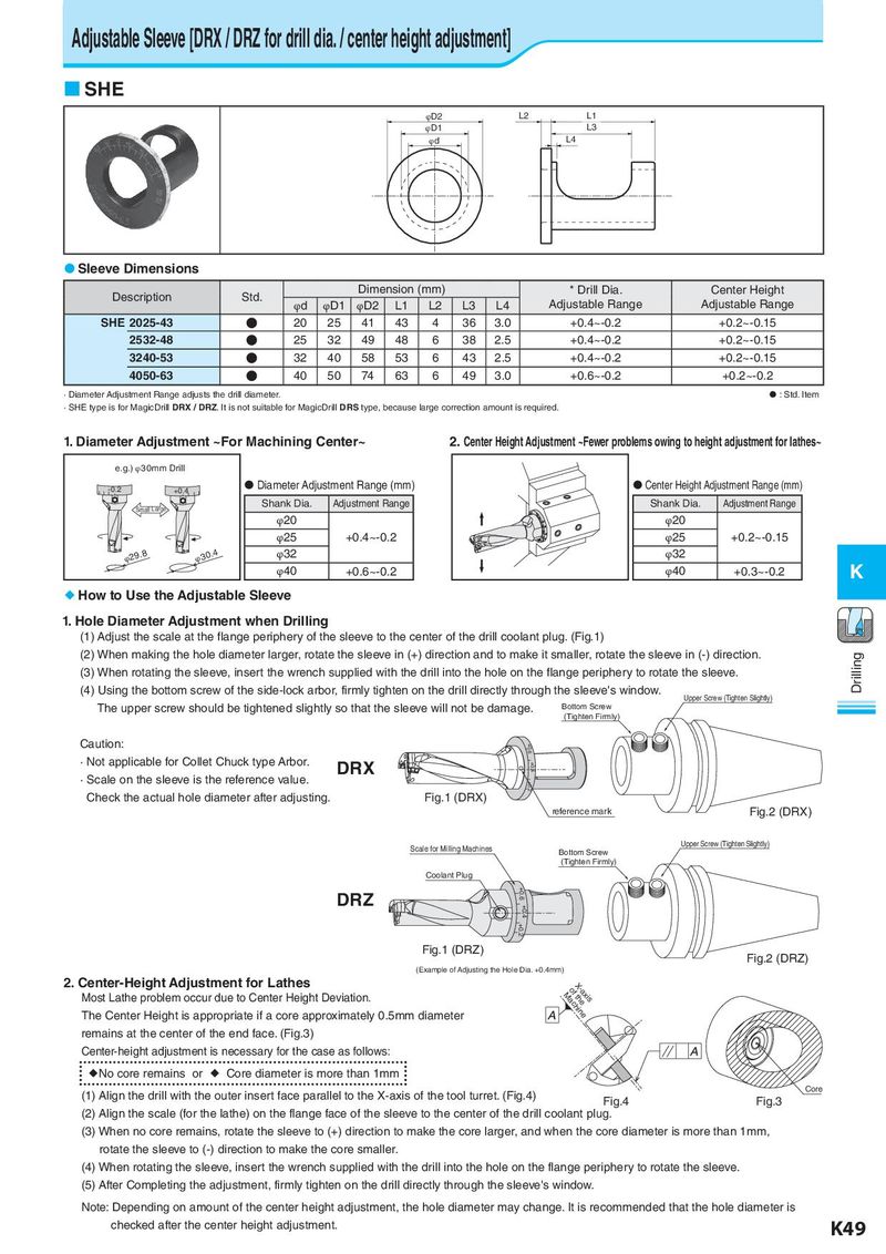
Adjustable Sleeve [DRX / DRZ for drill dia. / center height adjustment] SHE φD2 L2 L1 φD1 L3 φd L4 Sleeve Dimensions Description Std. Dimension (mm) * Drill Dia. Center Height φd φD1 φD2 L1 L2 L3 L4 Adjustable Range Adjustable Range SHE 2025-43 ● 20 25 41 43 4 36 3.0 +0.4~-0.2 +0.2~-0.15 2532-48 ● 25 32 49 48 6 38 2.5 +0.4~-0.2 +0.2~-0.15 3240-53 ● 32 40 58 53 6 43 2.5 +0.4~-0.2 +0.2~-0.15 4050-63 ● 40 50 74 63 6 49 3.0 +0.6~-0.2 +0.2~-0.2 · Diameter Adjustment Range adjusts the drill diameter. : Std. Item · SHE type is for MagicDrill DRX / DRZ. It is not suitable for MagicDrill DRS type, because large correction amount is required. 1. Diameter Adjustment ~For Machining Center~ 2. Center Height Adjustment ~Fewer problems owing to height adjustment for lathes~ e.g.) φ30mm Drill -0.2 +0.4 Diameter Adjustment Range (mm) Center Height Adjustment Range (mm) Small Large Shank Dia. Adjustment Range Shank Dia. Adjustment Range φ20 φ20 φ25 +0.4~-0.2 φ25 +0.2~-0.15 φ29.8 φ30.4 φ32 φ32 φ40 +0.6~-0.2 φ40 +0.3~-0.2 K How to Use the Adjustable Sleeve 1. Hole Diameter Adjustment when Drilling (1) Adjust the scale at the flange periphery of the sleeve to the center of the drill coolant plug. (Fig.1) (2) When making the hole diameter larger, rotate the sleeve in (+) direction and to make it smaller, rotate the sleeve in (-) direction. Drilling (3) When rotating the sleeve, insert the wrench supplied with the drill into the hole on the flange periphery to rotate the sleeve. (4) Using the bottom screw of the side-lock arbor, firmly tighten on the drill directly through the sleeve's window. Upper Screw (Tighten Slightly) The upper screw should be tightened slightly so that the sleeve will not be damage. Bottom Screw (Tighten Firmly) Caution: +0.6 · Not applicable for Collet Chuck type Arbor. DRX +0.4 · Scale on the sleeve is the reference value. +0.2 Check the actual hole diameter after adjusting. Fig.1 (DRX) reference mark Fig.2 (DRX) Scale for Milling Machines Upper Screw (Tighten Slightly) Bottom Screw (Tighten Firmly) Coolant Plug DRZ +0.6 +0.4 +0.2 Fig.1 (DRZ) Fig.2 (DRZ) (Example of Adjusting the Hole Dia. +0.4mm) 2. Center-Height Adjustment for Lathes X-oafxMtihsaechine Most Lathe problem occur due to Center Height Deviation. The Center Height is appropriate if a core approximately 0.5mm diameter remains at the center of the end face. (Fig.3) Center-height adjustment is necessary for the case as follows: No core remains or Core diameter is more than 1mm (1) Align the drill with the outer insert face parallel to the X-axis of the tool turret. (Fig.4) Core Fig.4 Fig.3 (2) Align the scale (for the lathe) on the flange face of the sleeve to the center of the drill coolant plug. (3) When no core remains, rotate the sleeve to (+) direction to make the core larger, and when the core diameter is more than 1mm, rotate the sleeve to (-) direction to make the core smaller. (4) When rotating the sleeve, insert the wrench supplied with the drill into the hole on the flange periphery to rotate the sleeve. (5) After Completing the adjustment, firmly tighten on the drill directly through the sleeve's window. Note: Depending on amount of the center height adjustment, the hole diameter may change. It is recommended that the hole diameter is checked after the center height adjustment. K49