Основной каталог Kyocera 2016-2017 - страница 535
Навигация
 Каталог Kyocera фрезы MFH для высокоскоростной обработки
 Каталог Kyocera фрезы MEC высокопроизводительные концевые и торцевые фрезы
 Каталог микроинструмента Kyocera 2015-2016
 Каталог Kyocera высокоэффективные сверла со сменными пластинами DRV
 Каталог Kyocera пластины TQ для нарезания резьбы c прессованным стружколомом
 Каталог Kyocera высокопроизводительные модульные сверла DRA
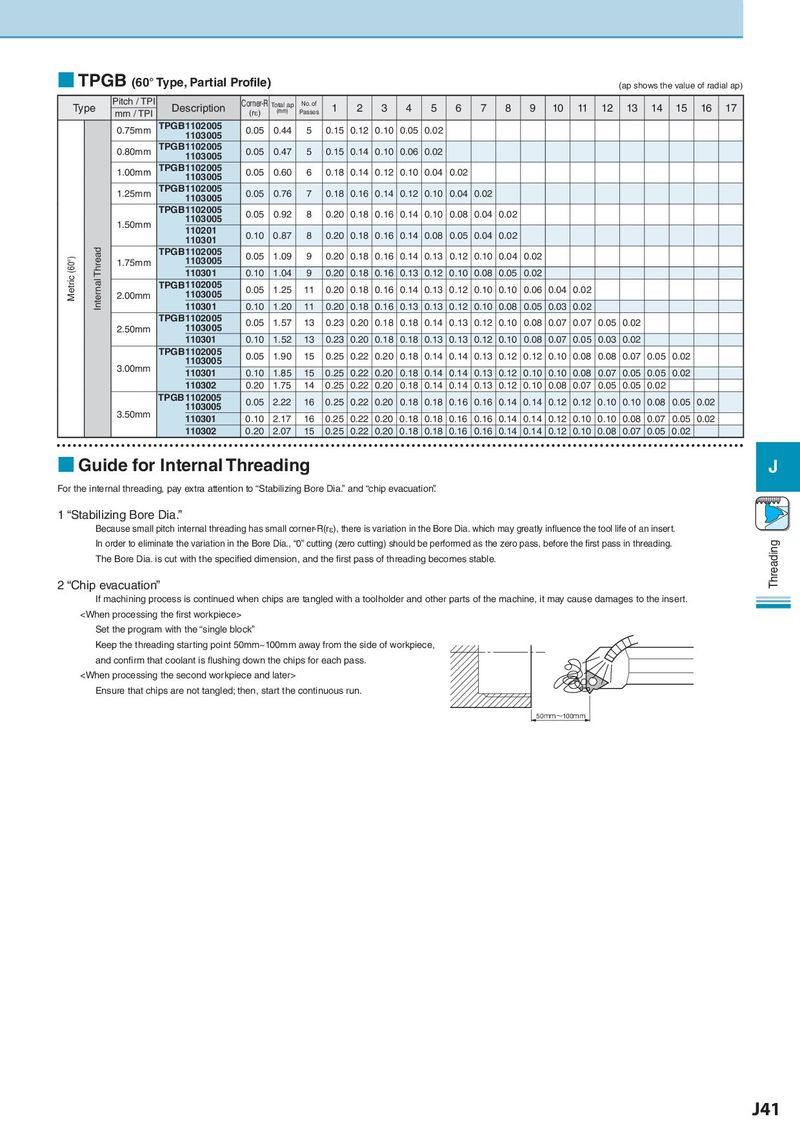
■ TPGB (60° Type, Partial Profile) (ap shows the value of radial ap)
Type Pitch / TPI Description Corner-R Total ap No. of 1 2 3 4 5 6 7 8 9 10 11 12 13 14 15 16 17
mm / TPI (rε) (mm) Passes
0.75mm TPGB1102005 0.05 0.44 5 0.15 0.12 0.10 0.05 0.02
1103005
0.80mm TPGB1102005 0.05 0.47 5 0.15 0.14 0.10 0.06 0.02
1103005
1.00mm TPGB1102005 0.05 0.60 6 0.18 0.14 0.12 0.10 0.04 0.02
1103005
1.25mm TPGB1102005 0.05 0.76 7 0.18 0.16 0.14 0.12 0.10 0.04 0.02
1103005
TPGB1102005 0.05 0.92 8 0.20 0.18 0.16 0.14 0.10 0.08 0.04 0.02
1.50mm 1103005
110201 0.10 0.87 8 0.20 0.18 0.16 0.14 0.08 0.05 0.04 0.02
110301
Metric (60°) Internal Thread TPGB1102005 0.05 1.09 9 0.20 0.18 0.16 0.14 0.13 0.12 0.10 0.04 0.02
1.75mm 1103005
110301 0.10 1.04 9 0.20 0.18 0.16 0.13 0.12 0.10 0.08 0.05 0.02
TPGB1102005 0.05 1.25 11 0.20 0.18 0.16 0.14 0.13 0.12 0.10 0.10 0.06 0.04 0.02
2.00mm 1103005
110301 0.10 1.20 11 0.20 0.18 0.16 0.13 0.13 0.12 0.10 0.08 0.05 0.03 0.02
TPGB1102005 0.05 1.57 13 0.23 0.20 0.18 0.18 0.14 0.13 0.12 0.10 0.08 0.07 0.07 0.05 0.02
2.50mm 1103005
110301 0.10 1.52 13 0.23 0.20 0.18 0.18 0.13 0.13 0.12 0.10 0.08 0.07 0.05 0.03 0.02
TPGB1102005 0.05 1.90 15 0.25 0.22 0.20 0.18 0.14 0.14 0.13 0.12 0.12 0.10 0.08 0.08 0.07 0.05 0.02
3.00mm 1103005
110301 0.10 1.85 15 0.25 0.22 0.20 0.18 0.14 0.14 0.13 0.12 0.10 0.10 0.08 0.07 0.05 0.05 0.02
110302 0.20 1.75 14 0.25 0.22 0.20 0.18 0.14 0.14 0.13 0.12 0.10 0.08 0.07 0.05 0.05 0.02
TPGB1102005 0.05 2.22 16 0.25 0.22 0.20 0.18 0.18 0.16 0.16 0.14 0.14 0.12 0.12 0.10 0.10 0.08 0.05 0.02
3.50mm 1103005
110301 0.10 2.17 16 0.25 0.22 0.20 0.18 0.18 0.16 0.16 0.14 0.14 0.12 0.10 0.10 0.08 0.07 0.05 0.02
110302 0.20 2.07 15 0.25 0.22 0.20 0.18 0.18 0.16 0.16 0.14 0.14 0.12 0.10 0.08 0.07 0.05 0.02
■ Guide for Internal Threading J
For the internal threading, pay extra attention to “Stabilizing Bore Dia.” and “chip evacuation”.
1 “Stabilizing Bore Dia.”
Because small pitch internal threading has small corner-R(rε), there is variation in the Bore Dia. which may greatly influence the tool life of an insert.
In order to eliminate the variation in the Bore Dia., “0” cutting (zero cutting) should be performed as the zero pass, before the first pass in threading. Threading
The Bore Dia. is cut with the specified dimension, and the first pass of threading becomes stable.
2 “Chip evacuation”
If machining process is continued when chips are tangled with a toolholder and other parts of the machine, it may cause damages to the insert.