Основной каталог Kyocera 2016-2017 - страница 472
Навигация
 Каталог Kyocera фрезы MFH для высокоскоростной обработки
 Каталог Kyocera фрезы MEC высокопроизводительные концевые и торцевые фрезы
 Каталог микроинструмента Kyocera 2015-2016
 Каталог Kyocera высокоэффективные сверла со сменными пластинами DRV
 Каталог Kyocera пластины TQ для нарезания резьбы c прессованным стружколомом
 Каталог Kyocera высокопроизводительные модульные сверла DRA
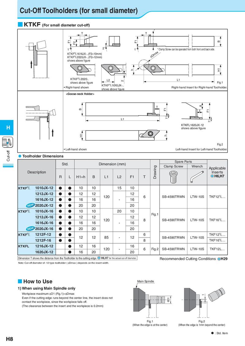
Cut-Off Toolholders (for small diameter)
■ KTKF (For small diameter cut-off)
*
T T
F1 F2 F1 B
1˚ 2˚ 1˚ * Clamp Screw can be operated from both front and back side.
KTKF&1616JX-..(F2=10mm) φDmax
KTKF&2020JX-..(F2=12mm)
shows above figure
h H1
KTKF&2020.. L2 2 L1
shows above figure Fig.1
• Right-hand shown KTKF&1010JX-.. Right-hand Insert for Right-hand Toolholder.
shows above figure