Основной каталог Kyocera 2016-2017 - страница 473
Навигация
 Каталог Kyocera фрезы MFH для высокоскоростной обработки
 Каталог Kyocera фрезы MEC высокопроизводительные концевые и торцевые фрезы
 Каталог микроинструмента Kyocera 2015-2016
 Каталог Kyocera высокоэффективные сверла со сменными пластинами DRV
 Каталог Kyocera пластины TQ для нарезания резьбы c прессованным стружколомом
 Каталог Kyocera высокопроизводительные модульные сверла DRA
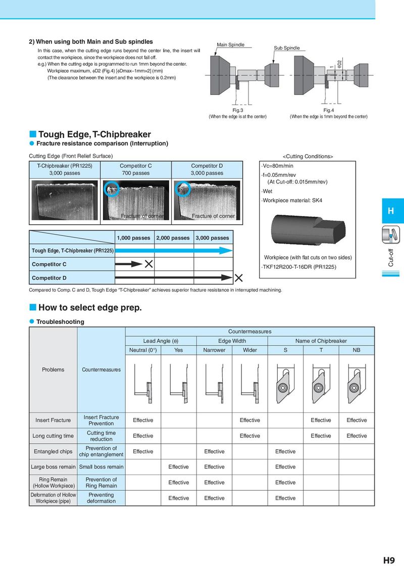
2) When using both Main and Sub spindles Main Spindle
In this case, when the cutting edge runs beyond the center line, the insert will Sub Spindle
contact the workpiece, since the workpiece does not fall off.
e.g.) When the cutting edge is programmed to run 1mm beyond the center. 1 φD2
Workpiece maximum, φD2 (Fig.4) [φDmax−1mm×2] (mm)
(The clearance between the insert and the workpiece is 0.2mm)
Fig.3 Fig.4
(When the edge is at the center) (When the edge is 1mm beyond the center)
Tough Edge, T-Chipbreaker
Fracture resistance comparison (Interruption)
Cutting Edge (Front Relief Surface)