Основной каталог Kyocera 2016-2017 - страница 463
Навигация
 Каталог Kyocera фрезы MFH для высокоскоростной обработки
 Каталог Kyocera фрезы MEC высокопроизводительные концевые и торцевые фрезы
 Каталог микроинструмента Kyocera 2015-2016
 Каталог Kyocera высокоэффективные сверла со сменными пластинами DRV
 Каталог Kyocera пластины TQ для нарезания резьбы c прессованным стружколомом
 Каталог Kyocera высокопроизводительные модульные сверла DRA
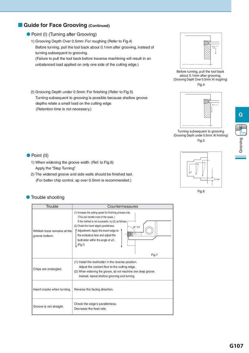
Guide for Face Grooving (Continued) Point (I) (Turning after Grooving) 1)Grooving Depth Over 0.5mm: For roughing (Refer to Fig.4) Before turning, pull the tool back about 0.1mm after grooving, instead of turning subsequent to grooving. (Failure to pull the tool back before traverse machining will result in an unbalanced load applied on only one side of the cutting edge.) Before turning, pull the tool back about 0.1mm after grooving. (Grooving Depth Over 0.5mm: At roughing) Fig.4 2) Grooving Depth under 0.5mm: For finishing (Refer to Fig.5) Turning subsequent to grooving is possible because shallow groove depths relate a small load on the cutting edge. (Retention time is not necessary.) G Turning subsequent to grooving (Grooving Depth under 0.5mm: At finishing) Fig.5 Grooving Point (II) 1) When widening the groove width. (Ref. to Fig.6) Apply the “Step Turning”. 2) The widened groove and side walls should be finished last. (For better chip control, ap over 0.5mm is recommended.) 0.1mm Fig.6 Trouble shooting Trouble Countermeasures (1) Increase the cutting speed for finishing process only. (This can handle most of the cases. ) If the method is not successful, try (2) as follows. (2) Check the insert edge’s parallelness. 90 °±5′ Whitish trace remains at the [ Adjustment: Apply the insert edge to ] groove bottom. the workpiece face and adjust the toolholder within the angle of ±5'. (Fig.7) Fig.7 (1) Install the toolholder in the reverse position. Chips are entangled. Adjust the coolant flow to the cutting edge. (2) When widening the groove, do not machine one deep groove. Instead, repeat shallow grooving and turning. Insert cracks when turning. Reverse the facing direction. Groove is not straight. Check the edge's parallelness. Decrease the feed rate. G107