Основной каталог Kyocera 2016-2017 - страница 462
Навигация
 Каталог Kyocera фрезы MFH для высокоскоростной обработки
 Каталог Kyocera фрезы MEC высокопроизводительные концевые и торцевые фрезы
 Каталог микроинструмента Kyocera 2015-2016
 Каталог Kyocera высокоэффективные сверла со сменными пластинами DRV
 Каталог Kyocera пластины TQ для нарезания резьбы c прессованным стружколомом
 Каталог Kyocera высокопроизводительные модульные сверла DRA
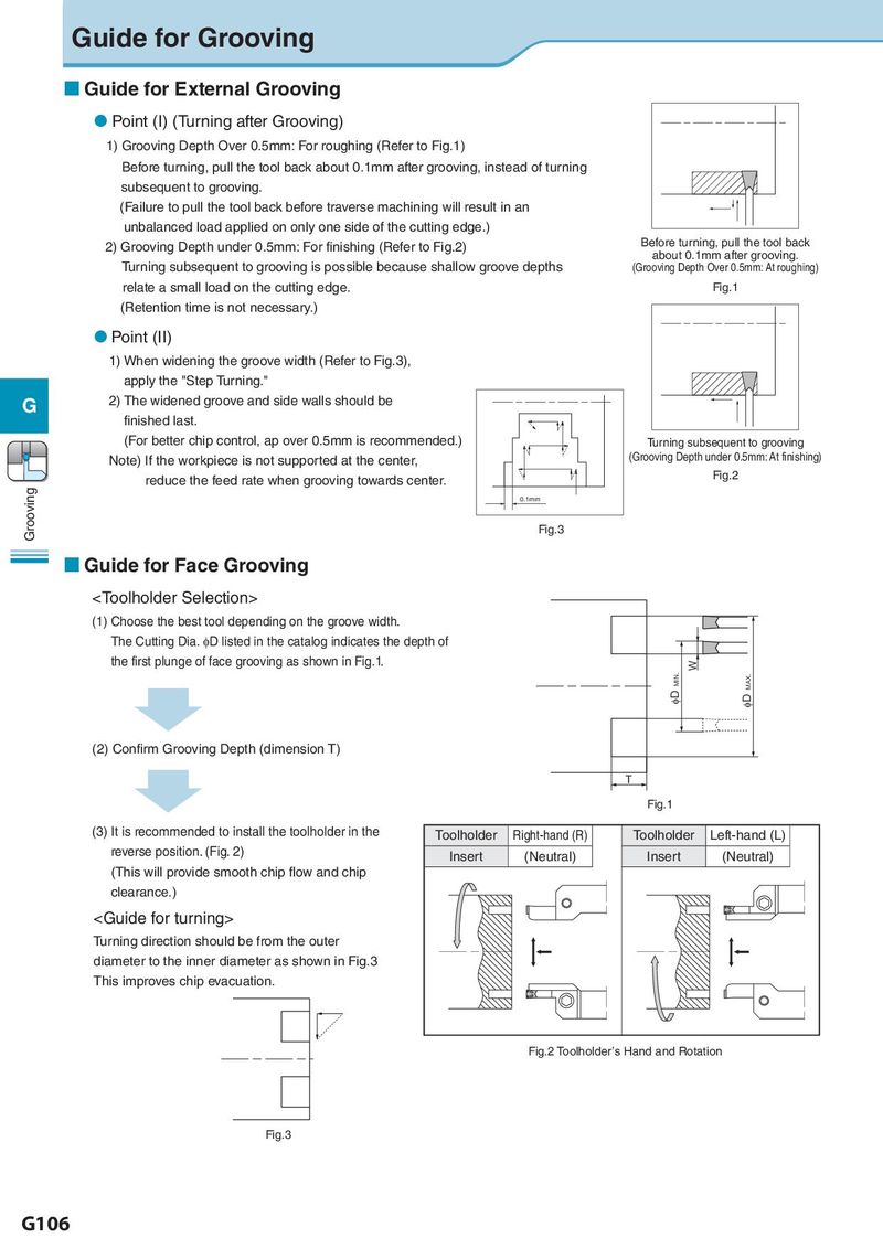
Guide for Grooving
Guide for External Grooving
Point (I) (Turning after Grooving)
1)Grooving Depth Over 0.5mm: For roughing (Refer to Fig.1)
Before turning, pull the tool back about 0.1mm after grooving, instead of turning
subsequent to grooving.
(Failure to pull the tool back before traverse machining will result in an
unbalanced load applied on only one side of the cutting edge.)
2) Grooving Depth under 0.5mm: For finishing (Refer to Fig.2) Before turning, pull the tool back
about 0.1mm after grooving.
Turning subsequent to grooving is possible because shallow groove depths (Grooving Depth Over 0.5mm: At roughing)
relate a small load on the cutting edge. Fig.1
(Retention time is not necessary.)
Point (II)
1)When widening the groove width (Refer to Fig.3),
apply the "Step Turning."
G 2)The widened groove and side walls should be
finished last.
(For better chip control, ap over 0.5mm is recommended.) Turning subsequent to grooving
Note) If the workpiece is not supported at the center, (Grooving Depth under 0.5mm: At finishing)
reduce the feed rate when grooving towards center. Fig.2
Grooving 0.1mm
Fig.3
Guide for Face Grooving