Основной каталог Kyocera 2016-2017 - страница 419
Навигация
 Каталог Kyocera фрезы MFH для высокоскоростной обработки
 Каталог Kyocera фрезы MEC высокопроизводительные концевые и торцевые фрезы
 Каталог микроинструмента Kyocera 2015-2016
 Каталог Kyocera высокоэффективные сверла со сменными пластинами DRV
 Каталог Kyocera пластины TQ для нарезания резьбы c прессованным стружколомом
 Каталог Kyocera высокопроизводительные модульные сверла DRA
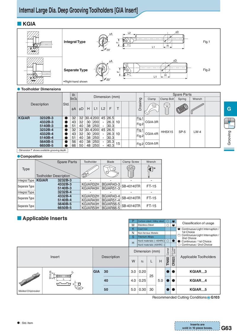
Internal Large Dia. Deep Grooving Toolholders [GIA Insert] KGIA IA L2 ID Integral Type F Fig.1 T H L1 20° IA ID Separate Type F Fig.2 T H L1 Right-hand shown 20° Toolholder Dimensions Min. Dimension (mm) Spare Parts Bore Dia. Drawing Clamp Clamp Bolt Spring Wrench Description Std. φA φD H L1 L2 F T G KGIAR 3232B-3 ● 32 32 30.4 200 45 26.5 Fig.1 4332B-3 ● 43 32 30 200 - 26.3 10 Fig.2 CGIA-3R 5140B-3 ● 51 40 38 250 - 30.3 3232B-4 ● 32 32 30.4 200 45 26.5 Fig.1 HH5X15 SP-5 LW-4 Grooving 4332B-4 ● 43 32 30 200 - 26.3 10 Fig.2 CGIA-4R 5140B-4 ● 51 40 38 250 - 30.3 5640B-5 ● 56 40 38 250 - 35.3 15 Fig.2 CGIA-5R 6650B-5 ● 66 50 48 250 - 40.3 · Dimension T shows available grooving depth. Composition Spare Parts Toolholder Blade Clamp Screw Wrench Type Toolholder Description Integral Type KGIAR 3232B-3 - - - - Separate Type 4332B-3 KGIAR32H BGIAR43-3 SB-40140TR FT-15 5140B-3 KGIAR40H BGIAR51-3 Integral Type 3232B-4 - - - - Separate Type 4332B-4 KGIAR32H BGIAR43-4 SB-40140TR FT-15 5140B-4 KGIAR40H BGIAR51-4 Separate Type 5640B-5 KGIAR40H BGIAR56-5 SB-40140TR FT-15 6650B-5 KGIAR50H BGIAR66-5 Applicable Inserts P Carbon steel / Alloy steel M Stainless Steel Classification of usage K Cast Iron :Continuous-Light Interruption / N Non-ferrous Metals 1st Choice S Titanium Alloys :Continuous-Light Interruption / 2nd Choice H Hard materials (~40HRC) ● ●: Continuous / 1st Choice Hard materials (40HRC~) : Continuous / 2nd Choice Dimension (mm) Cermet CVD Coated Carbide Insert Description TN60 CR9025 Applicable Toolholders W rε L H W±0.05 5゜ rH GIA 30 3.0 0.20 ● ● KGIAR…3 5゜ 25 L 40 4.0 0.25 5.0 ● ● KGIAR…4 H 120゜ 50 5.0 0.30 30 ● ● KGIAR…5 Molded Chipbreaker Recommended Cutting Conditions G103 : Std. Item Inserts are sold in 10 piece boxes. G63