Основной каталог Kyocera 2016-2017 - страница 41
Навигация
 Каталог Kyocera фрезы MFH для высокоскоростной обработки
 Каталог Kyocera фрезы MEC высокопроизводительные концевые и торцевые фрезы
 Каталог микроинструмента Kyocera 2015-2016
 Каталог Kyocera высокоэффективные сверла со сменными пластинами DRV
 Каталог Kyocera пластины TQ для нарезания резьбы c прессованным стружколомом
 Каталог Kyocera высокопроизводительные модульные сверла DRA
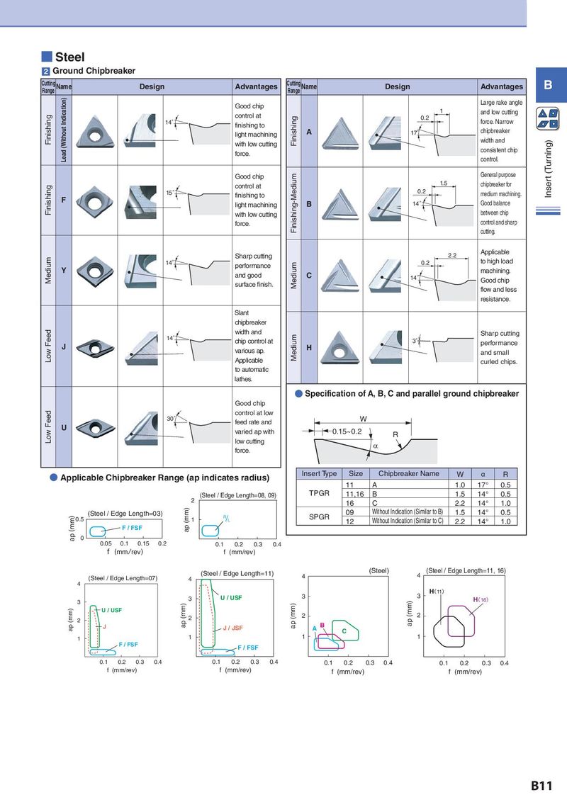
■ Steel 2 Ground Chipbreaker Cutting Name Design Advantages Cutting Name Design Advantages B Range Range Lead (Without Indication) Good chip Large rake angle control at 1 and low cutting Finishing 14° Finishing 0.2 force. Narrow finishing to chipbreaker light machining A 17° with low cutting width and Insert (Turning) force. consistent chip control. Good chip Finishing-Medium General purpose Finishing control at 1.5 chipbreaker for 15° finishing to 0.2 medium machining. F light machining B 14° Good balance with low cutting between chip force. control and sharp cutting. Sharp cutting 2.2 Applicable Medium 14° performance Medium 0.2 to high load Y and good C machining. 14° Good chip surface finish. flow and less resistance. Slant chipbreaker Low Feed width and Medium Sharp cutting 14° chip control at 3° performance J various ap. H and small Applicable curled chips. to automatic lathes. ● Specification of A, B, C and parallel ground chipbreaker Good chip Low Feed control at low 30° feed rate and W U varied ap with 0.15~0.2 R low cutting D force. ● Applicable Chipbreaker Range (ap indicates radius) Insert Type Size Chipbreaker Name W α R 11 A 1.0 17° 0.5 (mm)(Steel / Edge Length=08, 09) TPGR 11,16 B 1.5 14° 0.5 2 16 C 2.2 14° 1.0 (mm) (Steel / Edge Length=03) ap (mm) SPGR 09 Without Indication (Similar to B) 1.5 14° 0.5 ap (mm) 0.5 1 & 12 Without Indication (Similar to C) 2.2 14° 1.0 F / FSF 0 0.05 0.1 0.15 0.2 0.1 0.2 0.3 0.4 f (mm/rev) f (mm/rev) (mm) (Steel / Edge Length=11) (mm) (Steel) (mm) (Steel / Edge Length=11, 16) (mm) (Steel / Edge Length=07) 4 4 4 4 3 3 H(11) 3 3 U / USF ap (mm) H(16) ap (mm) U / USF ap (mm) ap (mm) 2 2 2 2 J J / JSF A B C 1 1 1 1 F / FSF F / FSF 0.1 0.2 0.3 0.4 0.1 0.2 0.3 0.4 0.1 0.2 0.3 0.4 0.1 0.2 0.3 0.4 f (mm/rev) f (mm/rev) f (mm/rev) f (mm/rev) B11