Основной каталог Kyocera 2016-2017 - страница 42
Навигация
 Каталог Kyocera фрезы MFH для высокоскоростной обработки
 Каталог Kyocera фрезы MEC высокопроизводительные концевые и торцевые фрезы
 Каталог микроинструмента Kyocera 2015-2016
 Каталог Kyocera высокоэффективные сверла со сменными пластинами DRV
 Каталог Kyocera пластины TQ для нарезания резьбы c прессованным стружколомом
 Каталог Kyocera высокопроизводительные модульные сверла DRA
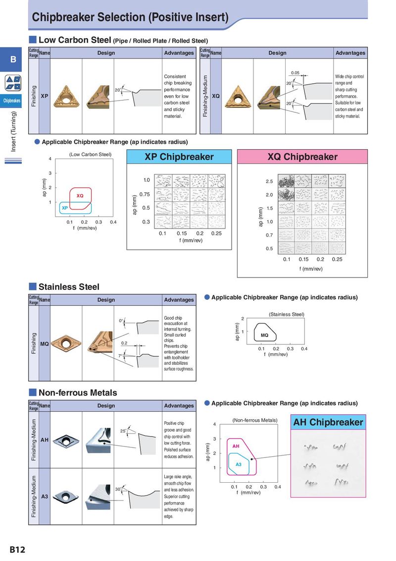
Chipbreaker Selection (Positive Insert) ■ Low Carbon Steel (Pipe / Rolled Plate / Rolled Steel) Cutting Name Design Advantages Cutting Name Design Advantages B Range Range Consistent 0.05 Wide chip control chip breaking Finishing-Medium 20° range and Finishing 20° performance sharp cutting XP even for low XQ performance. Chipbreakers carbon steel 20° Suitable for low (Turning) and sticky carbon steel and material. sticky material. Inser t ● Applicable Chipbreaker Range (ap indicates radius) (mm) (Low Carbon Steel) XP Chipbreaker XQ Chipbreaker 4 3 (mm) 1.0 2.5 2 ap XQ (mm) 0.75 2.0 1 XP ap 0.5 (mm) 1.5 0.1 0.2 0.3 0.4 0.3 ap 1.0 f (mm/rev) 0.1 0.15 0.2 0.25 0.7 f (mm/rev) 0.5 0.1 0.15 0.2 0.25 f (mm/rev) ■ Stainless Steel Cutting Name Design Advantages ● Applicable Chipbreaker Range (ap indicates radius) Range (mm) (Stainless Steel) 0° Good chip 2 evacuation at ap (mm) internal turning. 1 Finishing Small curled MQ MQ 0.2 chips. Prevents chip 0.1 0.2 0.3 0.4 7° entanglement f (mm/rev) with toolholder and stabilizes surface roughness. ■ Non-ferrous Metals Cutting Name Design Advantages ● Applicable Chipbreaker Range (ap indicates radius) Range Finishing-Medium (mm) (Non-ferrous Metals) AH Chipbreaker Positive chip 4 25° groove and good AH chip control with 3 low cutting force. ap (mm) AH Polished surface 2 reduces adhesion. 1 A3 Finishing-Medium Large rake angle, smooth chip flow 0.1 0.2 0.3 0.4 30° and less adhesion. f (mm/rev) A3 Superior cutting performance achieved by sharp edge. B12