Основной каталог Kyocera 2016-2017 - страница 40
Навигация
 Каталог Kyocera фрезы MFH для высокоскоростной обработки
 Каталог Kyocera фрезы MEC высокопроизводительные концевые и торцевые фрезы
 Каталог микроинструмента Kyocera 2015-2016
 Каталог Kyocera высокоэффективные сверла со сменными пластинами DRV
 Каталог Kyocera пластины TQ для нарезания резьбы c прессованным стружколомом
 Каталог Kyocera высокопроизводительные модульные сверла DRA
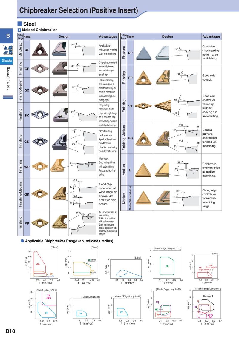
Chipbreaker Selection (Positive Insert) ■ Steel 1 Molded Chipbreaker B Cutting Name Design Advantages Cutting Name Design Advantages Range Range Minute ap 20° Available for Finishing Consistent CF minute ap (0.02 to 14° chip breaking 0.2mm) finishing. DP performance Chipbreakers for finishing. Finishing Chips fragmented Insert (Turning) 7.5° in small pieces GF in machining of small ap. Finishing 20° Good chip Finishing-Medium Enables machining GP control. over a wide range of 5° conditions by using the GQ optimum chipbreaker width according to the Good chip cutting depth. Finishing 13° control for Sharp cutting VF varied ap Finishing performance due to such as 18° Large rake angle. Large 3° copying and SK dot to the corner edge undercutting. improved chip control in a wide feed rate range. Finishing-Medium 0.2 15° 13° Good cutting 5° General Finishing performance. purpose Applicable without HQ chipbreaker CK 0.2 15° for medium 20° hand for two direction machining 5° machining. on automatic lathe. Wiper insert. Finishing 0° 10° Good surface finish at 0.15 Chipbreaker WP high feed machining Medium for short chips Reduces surface finish G 5° 10° at medium galling machining. Finishing-Medium 0.1 Good chip 17° evacuation at Standard (Without Indication) wide range by 0.2 Strong edge GK 0.1 breaker dot Medium chipbreaker 6° for medium and wide chip machining 17° pocket. range. 0.05 1st. Recommendation at 10° steel finishing. Finishing Stable chip control in a PP wide feed rate range. 5° Stable tool life due to special edge design with sharpness and improved strength. ● Applicable Chipbreaker Range (ap indicates radius) (mm) (Steel) (mm) (Steel) (mm) (Steel / Edge Length=07, 11) 5 5 4 (mm) 4 (Steel) ap (mm) 4 ap (mm) 4 (mm) (Steel) 3 CK General 3 ap (mm) purpose 3 3 3 ap (mm) GQ (mm) 2 2 GK PP 2 2 2 PP (Edge Length=11) SK (Edge Length=07) 1 1 Finishing ap 1 1 1 GF WP CF 0.05 0.1 0.15 0.2 0.05 0.1 0.15 0.2 0.1 0.2 0.3 0.4 0.5 0.1 0.2 0.3 0.4 0.1 0.2 0.3 0.4 f (mm/rev) f (mm/rev) f (mm/rev) f (mm/rev) f (mm/rev) (mm) (mm) (Steel / Edge Length=11) (mm) (Steel / Edge Length=11) 0.4 (Steel / Edge Length=08, 09) 4 4 XP (mm) (Edge Length=11) (mm) (Steel / Edge Length=16) Standard 0.3 (GP) 3 3 3 3 ap (mm) ap (mm) XQ ap (mm) G 0.2 (mm) 2 (mm) 2 2 2 HQ HQ 1 0.1 CF ap 1 ap 1 VF 1 VF XP (DP) GP 0.05 0.1 0.15 0.1 0.2 0.3 0.4 0.1 0.2 0.3 0.4 0.1 0.2 0.3 0.4 0.1 0.2 0.3 0.4 f (mm/rev) f (mm/rev) f (mm/rev) f (mm/rev) f (mm/rev) B10