Основной каталог Kyocera 2016-2017 - страница 39
Навигация
 Каталог Kyocera фрезы MFH для высокоскоростной обработки
 Каталог Kyocera фрезы MEC высокопроизводительные концевые и торцевые фрезы
 Каталог микроинструмента Kyocera 2015-2016
 Каталог Kyocera высокоэффективные сверла со сменными пластинами DRV
 Каталог Kyocera пластины TQ для нарезания резьбы c прессованным стружколомом
 Каталог Kyocera высокопроизводительные модульные сверла DRA
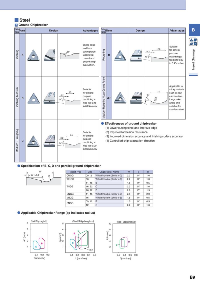
■ Steel 2 Ground Chipbreaker Cutting Name Design Advantages Cutting Name Design Advantages B Range Range Sharp edge Suitable and less Roughing 2.8 for general (Turning) Finishing 15° cutting force. 0.2 purpose S Good chip D 10° machining at control and feed rate 0.30 smooth chip to 0.45mm/rev. Inser t evacuation. Force Finishing-Medium Cutting Applicable to Suitable sticky material 1.5 for general Low 3.2 such as low 0.2 purpose 37° carbon steel. B 14° machining at Medium-Roughing / 25R R2.5 Large rake feed rate 0.15 angle and to 0.25mm/rev. suitable for stainless steel. ● Effectiveness of ground chipbreaker Medium - Roughing (1) Lower cutting force and improve edge Suitable (2) Improved adhesion resistance 2.2 for general (3) Improved dimension accuracy and finishing surface accuracy 0.2 purpose C machining at (4) Controlled chip evacuation direction 14° feed rate 0.20 to 0.35mm/rev. ● Specification of B, C, D and parallel ground chipbreaker W Insert Type Size Chipbreaker Name W α R 0.1~0.2 R CNGG 09,12 Without Indication (Similar to C) 2.2 14° 1.0 D WNGG 06 Without Indication (Similar to C) 2.2 14° 1.0 11, 16 B 1.5 14° 0.5 TNGG 16, 22 C 2.2 14° 1.0 ブレーカ W D R 16, 22 D 2.8 10° 1.5 B 1.5 14゜ 0.5 DNGG 11, 15 Without Indication (Similar to C) 2.5 14° 2.0 C 2.2 14゜ 1.0 VNGG 16 Without Indication (Similar to B) 1.5 14° 0.5 D 2.8 10゜ 1.5 09, 12 B 1.5 14° 0.5 SNGG 12 C 2.2 14° 1.0 ● Applicable Chipbreaker Range (ap indicates radius) (Steel / Edge Length=11) (mm) (Steel / Edge Length=16) (mm) 5 5 10 (Steel / Edge Length=22) 4 4 C 8 ap (mm) 3 ap (mm) 3 B ap (mm) 6 2 2 4 D B S C 1 S 1 2 25R 0.1 0.2 0.3 0.1 0.2 0.3 0.4 0.5 0.2 0.4 0.6 0.8 f (mm/rev) f (mm/rev) f (mm/rev) B9