Основной каталог Kyocera 2016-2017 - страница 37
Навигация
 Каталог Kyocera фрезы MFH для высокоскоростной обработки
 Каталог Kyocera фрезы MEC высокопроизводительные концевые и торцевые фрезы
 Каталог микроинструмента Kyocera 2015-2016
 Каталог Kyocera высокоэффективные сверла со сменными пластинами DRV
 Каталог Kyocera пластины TQ для нарезания резьбы c прессованным стружколомом
 Каталог Kyocera высокопроизводительные модульные сверла DRA
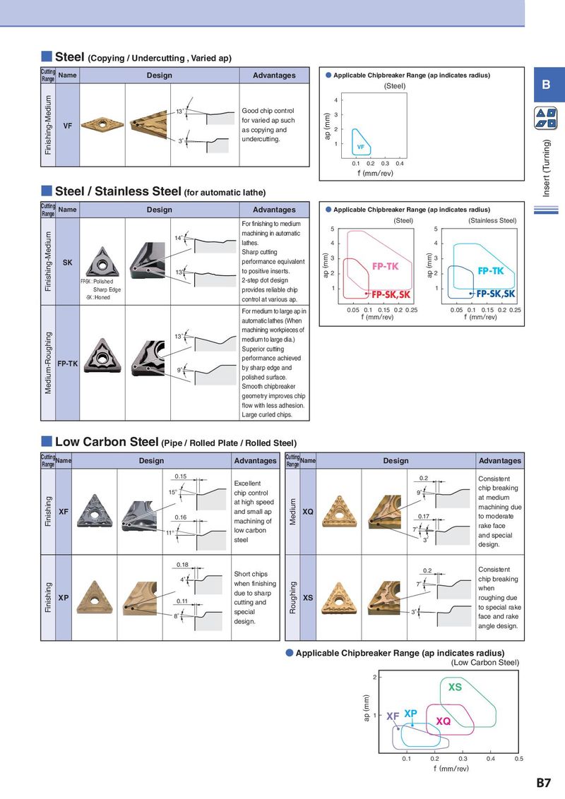
■ Steel (Copying / Undercutting , Varied ap) Cutting Name Design Advantages ● Applicable Chipbreaker Range (ap indicates radius) Range B (Steel) Finishing-Medium 4 13° Good chip control (mm) 3 VF for varied ap such as copying and ap 2 3° undercutting. 1 (Turning) VF 0.1 0.2 0.3 0.4 f (mm/rev) Inser t ■ Steel / Stainless Steel (for automatic lathe) Cutting Name Design Advantages ● Applicable Chipbreaker Range (ap indicates radius) Range For finishing to medium (Steel) (Stainless Steel) Finishing-Medium machining in automatic 5 5 14° lathes. 4 4 Sharp cutting (mm) (mm) SK performance equivalent 3 3 13° to positive inserts. ap 2 FP-TK ap 2 FP-TK FP-SK:Polished 2-step dot design Sharp Edge provides reliable chip 1 1 FP-SK,SK -SK:Honed control at various ap. FP-SK,SK For medium to large ap in 0.05 0.1 0.15 0.2 0.25 0.05 0.1 0.15 0.2 0.25 automatic lathes (When f (mm/rev) f (mm/rev) Medium-Roughing machining workpieces of 13° medium to large dia.) Superior cutting FP-TK performance achieved 9° by sharp edge and polished surface. Smooth chipbreaker geometry improves chip flow with less adhesion. Large curled chips. ■ Low Carbon Steel (Pipe / Rolled Plate / Rolled Steel) CRuatntigneg Name Design Advantages CRuatntigneg Name Design Advantages 0.15 0.2 Consistent Excellent chip breaking 15° chip control 9° at medium Finishing at high speed Medium machining due XF and small ap XQ 0.17 to moderate 0.16 machining of low carbon 7° rake face 11° and special steel 3° design. 0.18 Consistent Short chips 0.2 4° when finishing Roughing 7° chip breaking Finishing due to sharp when XP 0.11 cutting and XS roughing due special 3° to special rake 8° design. face and rake angle design. ● Applicable Chipbreaker Range (ap indicates radius) (Low Carbon Steel) 2 XS ap (mm) 1 XF XP XQ 0.1 0.2 0.3 0.4 0.5 f (mm/rev) B7