Основной каталог Kyocera 2016-2017 - страница 230
Навигация
 Каталог Kyocera фрезы MFH для высокоскоростной обработки
 Каталог Kyocera фрезы MEC высокопроизводительные концевые и торцевые фрезы
 Каталог микроинструмента Kyocera 2015-2016
 Каталог Kyocera высокоэффективные сверла со сменными пластинами DRV
 Каталог Kyocera пластины TQ для нарезания резьбы c прессованным стружколомом
 Каталог Kyocera высокопроизводительные модульные сверла DRA
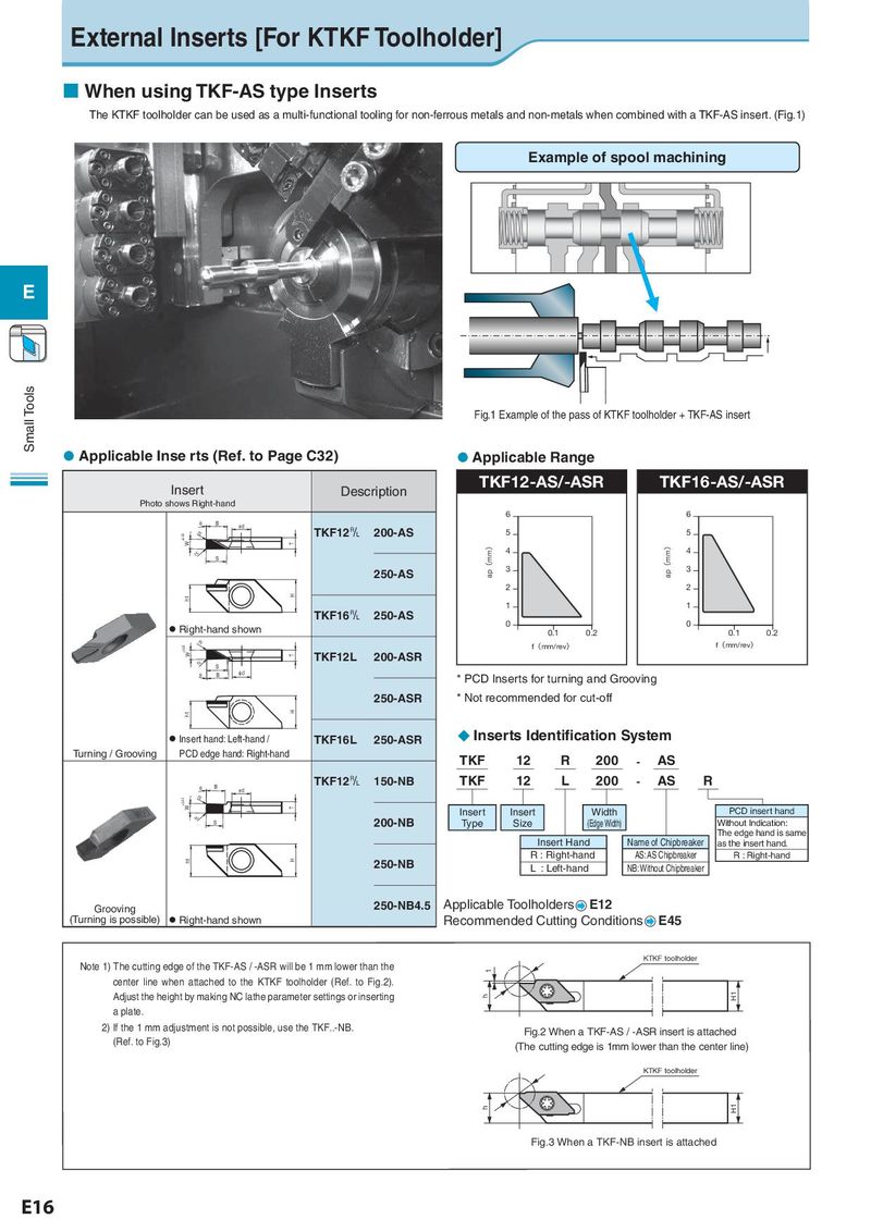
External Inserts [For KTKF Toolholder] ¢ When using TKF-AS type Inserts The KTKF toolholder can be used as a multi-functional tooling for non-ferrous metals and non-metals when combined with a TKF-AS insert. (Fig.1) Example of spool machining E Small Tools Fig.1 Example of the pass of KTKF toolholder + TKF-AS insert l Applicable Inse rts (Ref. to Page C32) lApplicable Range Insert Description TKF12-AS/-ASR TKF16-AS/-ASR Photo shows Right-hand 6 6 T B Id ±0.03 rH TKF12& 200-AS 5 5 W T ap(mm) ap(mm) rH 4 4 S 250-AS 3 3 2 2 h1 H 1 1 TKF16& 250-AS 0 0 l Right-hand shown 0.1 0.2 0.1 0.2 rH f(mm/rev) f(mm/rev) ±0.03 W T TKF12L 200-ASR rH S T B Id * PCD Inserts for turning and Grooving 250-ASR * Not recommended for cut-off h1 H l Insert hand: Left-hand / TKF16L 250-ASR u Inserts Identification System Turning / Grooving PCD edge hand: Right-hand TKF 12 R 200 - AS T B TKF12& 150-NB TKF 12 L 200 - AS R Id ±0.03 rH W T Insert Insert Width PCD insert hand rH S 200-NB Type Size (Edge Width) Without Indication: The edge hand is same Insert Hand Name of Chipbreaker as the insert hand. h1 H R : Right-hand AS: AS Chipbreaker R : Right-hand 250-NB L : Left-hand NB: Without Chipbreaker Grooving 250-NB4.5 Applicable Toolholders E12 (Turning is possible) l Right-hand shown Recommended Cutting Conditions E45 KTKF toolholder Note 1) The cutting edge of the TKF-AS / -ASR will be 1 mm lower than the 1 center line when attached to the KTKF toolholder (Ref. to Fig.2). Adjust the height by making NC lathe parameter settings or inserting h H1 a plate. 2) If the 1 mm adjustment is not possible, use the TKF..-NB. Fig.2 When a TKF-AS / -ASR insert is attached (Ref. to Fig.3) (The cutting edge is 1mm lower than the center line) KTKF toolholder h H1 Fig.3 When a TKF-NB insert is attached E16