Токарные станки KOVOSVIT серии SPH / ROLLER - страница 5
Навигация
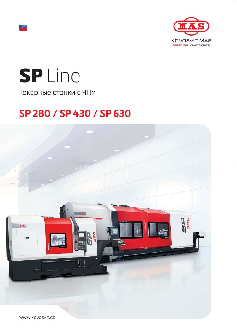 Токарные станки KOVOSVIT серии SP
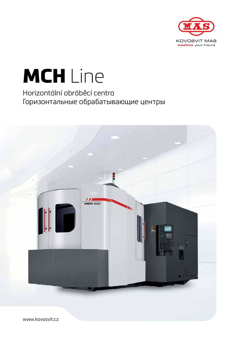 Фрезерные станки KOVOSVIT серии MCH
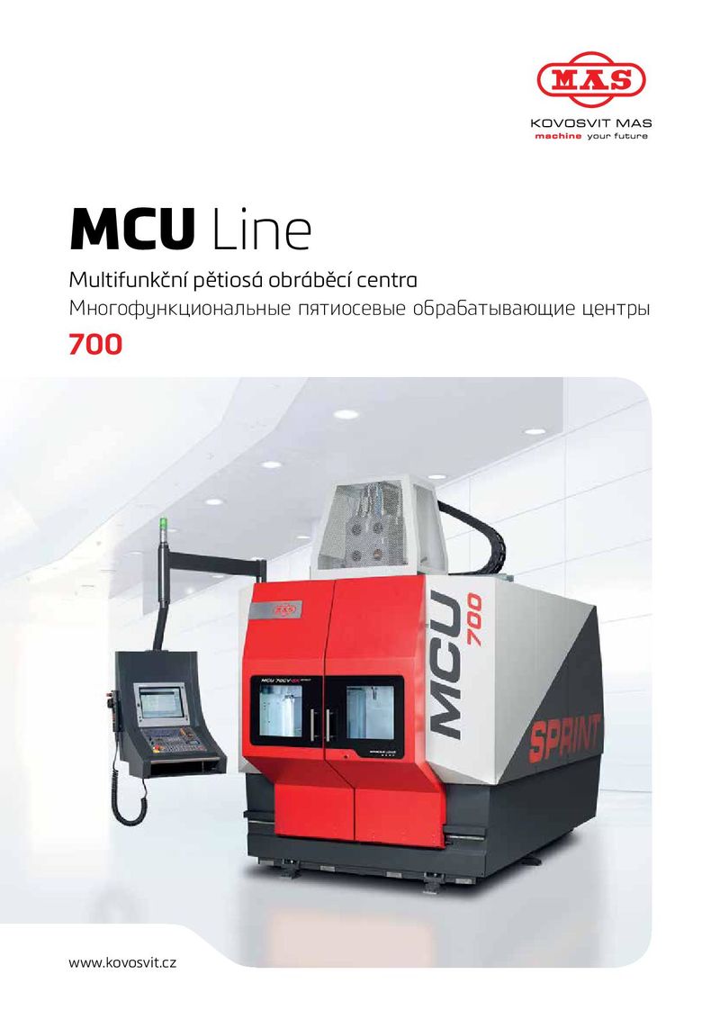 Фрезерные станки KOVOSVIT серии MCU 700
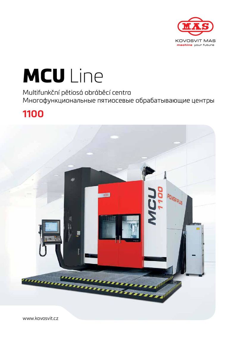 Фрезерные станки KOVOSVIT серии MCU 1100
 Фрезерные станки KOVOSVIT серии MCV
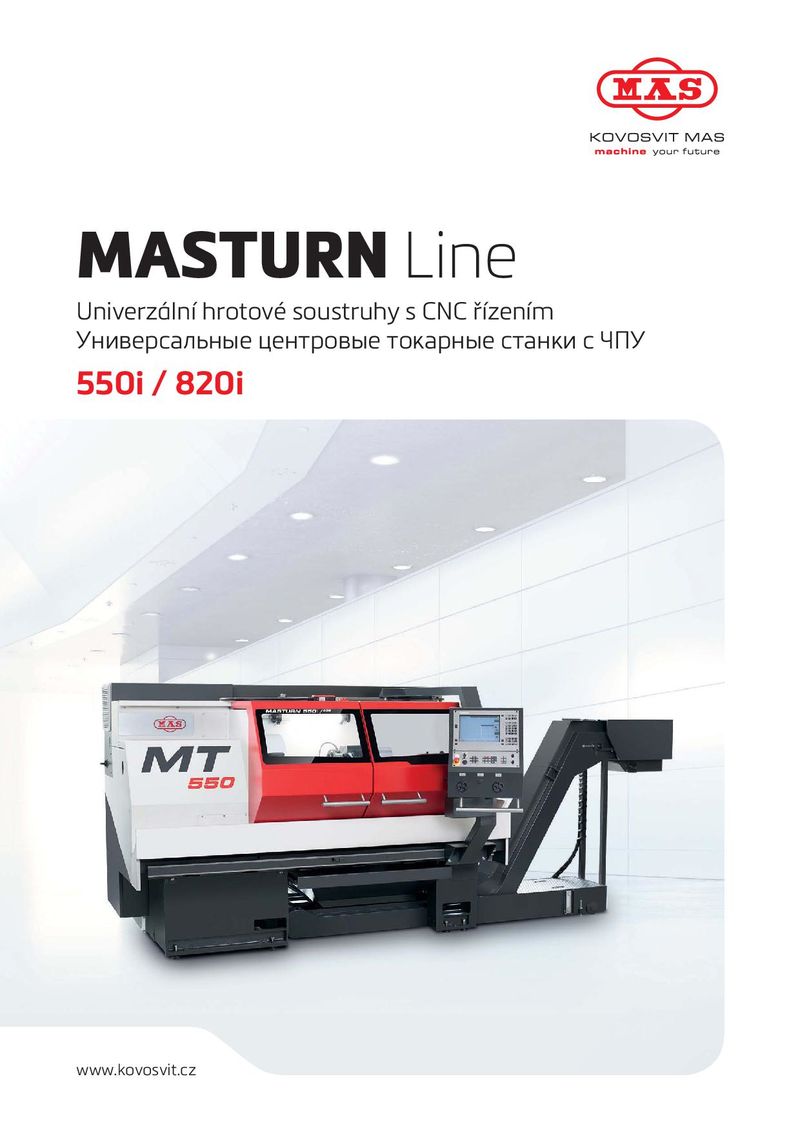 Токарные станки KOVOSVIT серии MASTURN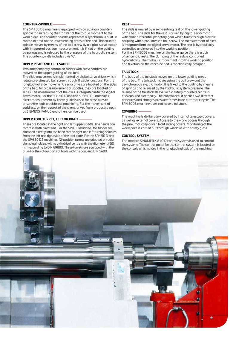
| COUNTER-SPINDLE— | REST— |
| The SPH 50 DS machine is equipped with an auxiliary counter- | The slide is moved by a self-centring rest on the lower guiding |
| spindle for increasing the transfer of the torque moment to the | of the bed. The slide for the rest is driven by digital servo motor |
| work piece. The counter-spindle represents a synchronous built-in | with front differential planetary gear which turns through fl exible |
| motor located on the lower leading areas of the bed. The counter- | coupling with a pre-stressed ball screw. The measurement of axes |
| spindle moves by means of the ball screw by a digital servo motor | is integrated into the digital servo motor. The rest is hydraulically |
| with integrated position measurement. It is fi xed on the guiding | controlled and moved into the working position. |
| by springs and is released by the pressure of the hydraulic system. | For the SPH 50DS machine on the lower guide there is a pair |
| The counter-spindle includes axis “C”. | of selfcentric rests. The clamping of the rests is controlled |
| hydraulically. The hydraulic movement into the working position | |
| UPPER RIGHT AND LEFT SADDLE— | and fi xation on the machine bed is mechanically designed. |
| Two independently controlled sliders with cross saddles are | |
| moved on the upper guiding of the bed. | TAILSTOCK— |
| The slide movement is implemented by digital servo drives which | The body of the tailstock moves on the lower guiding areas |
| rotate pre-stressed ball screwthrough fl exible junctions. For the | of the bed. The tailstock moves using the ball crew and the |
| longitudinal slide movement, servo drives are located on the sides | asynchronous electric motor. It is fi xed to the guiding by means |
| of the bed; for cross movement of saddles, they are located on | of springs and released by the hydraulic system pressure. The |
| slides. The measurement of the axes is integrated into the digital | release of the tailstock sleeve with a rotary mounted centre is |
| servo motor. For the SPH 50 D and the SPH 50 DS machines | also ensured electrically. The control circuit applies two different |
| direct measurement by linear guide is used for cross axes to | pressures and changes pressure forces in an automatic cycle. The |
| ensure the high precision of machining. For the movement of | SPH 50DS machine does not have a tailstock. |
| saddless, on the request of the client, drives from producers such | |
| as SIEMENS, FANUC and others can be used. | COVERING— |
| The machine is deliberately covered by internal telescopic covers, | |
| UPPER TOOL TURRET, LEFT OR RIGHT— | as well as external covers. Access to the workspace is through |
| These are located in the right and left upper saddle. The heads can | the pneumatically driven front sliding covers. Monitoring of the |
| rotate in both directions. For the SPH 50 machine, the blades are | workspace is carried out through windows with safety glass. |
| clamped directly into the head for the right and left turning spindles, | |
| from the left and right side of the tool plate. For the SPH 50 D and | CONTROL SYSTEM— |
| the SPH 50 DS machines, 12-position turrets are adapted or radial | The modern SINUMERIK 840 D control system is used to control |
| clamping holders with a cylindrical centre with the diameter of 50 | the system. The control panel for the control system is located on |
| mm according to DIN 69880. These turrets are equipped with the | the console which slides in the longitudinal axis of the machine. |
drive for the rotary parts of tools with the coupling DIN 5480.