Токарные станки KOVOSVIT серии SPH / ROLLER - страница 4
Навигация
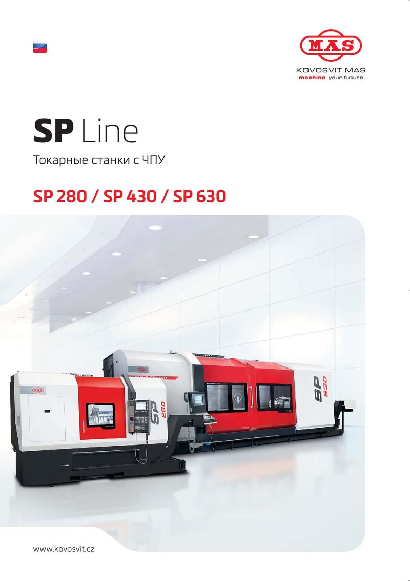 Токарные станки KOVOSVIT серии SP
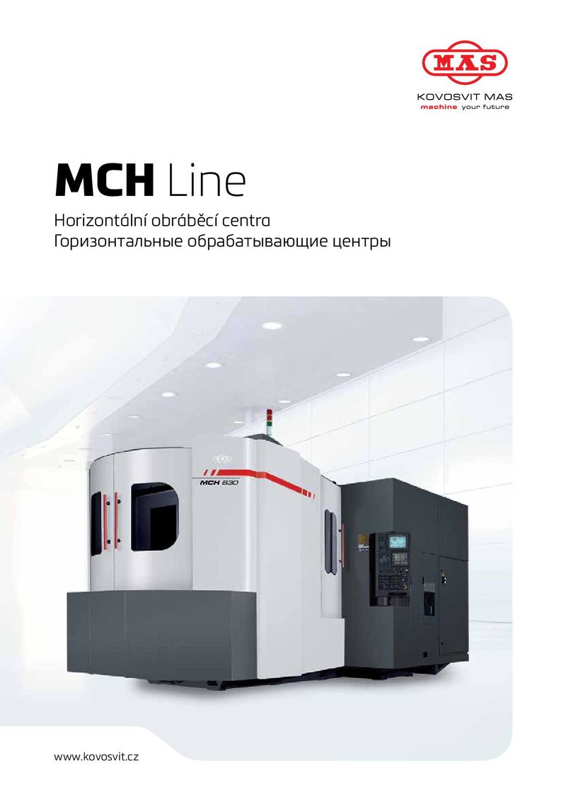 Фрезерные станки KOVOSVIT серии MCH
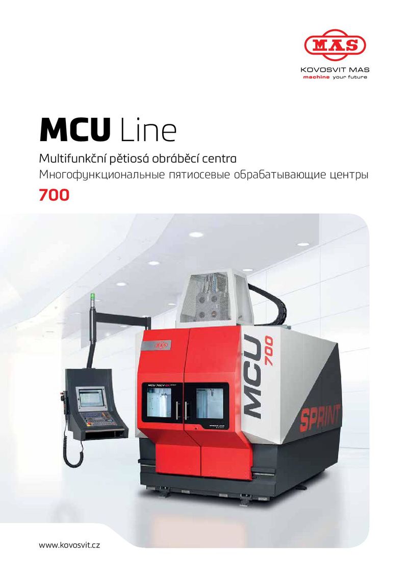 Фрезерные станки KOVOSVIT серии MCU 700
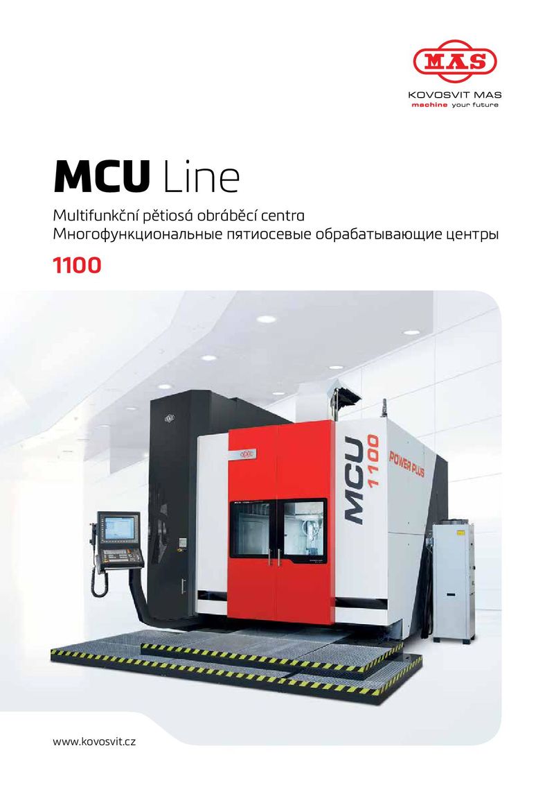 Фрезерные станки KOVOSVIT серии MCU 1100
 Фрезерные станки KOVOSVIT серии MCV
 Токарные станки KOVOSVIT серии MASTURN
Basic concept of machines SPH 50, SPH 50D, SPH 50DS The machines are equipped with two independently controlled saddles which enable machining with two tools at the same time. The turrets are located on cross saddles on the upper guiding of the bed and are mirror-oriented, faced with the tool plates. The turrets are 8-positioned in the SPH 50, or 12-positioned in the SPH 50D and the SPH 50 DS. They are electrically controlled and in SPH 50D and SPH 50DS have the option to use driven tools. The left turret moves to the space above the headstock, the right above the tailstock. Travels in axis Z are partially overlapped, however the minimum distance between the fl ange faces of the turrets is 400mm for SPH 50, (320 mm for SPH 50D and SPH 50DS). BED AND BASE— SPINDLE DRIVE— The cast bed is a box concept. The leading areas are declined The SPH 50 spindle drive is designed by AC regulation electric by 30° from the vertical position. The upper leading area is motor, two-speed gearbox and a reducer which transfers steel, hardened (hardness 600-730 Hv) and grinded. The lower torque moment to the spindle by toothed wheels. The gearbox is leading areas are a combination of hardened, steel and cast mounted on the reducer input. Gears are engaged by electrically lines (400 HB). The bed is mounted to the cast iron base fi lled controlled movements. The transfer of torque moment from with forming substance. On the base there are fi xation areas the electric motor to the input into the gearbox is activated by for the base of the main motor, the covering and for the load- V-belts. For the SPH 50D and the SPH 50DS machines, the drive bearing constructions of the machine nodes. On the upper bed is designed by a two-speed gearbox on the face of the motor and there are electric conductors and individual piping that are easily the belt gear to the spindle. accessible for the service and maintenance staff. The condensate and lubrication oil are collected back into the fi ller for the chip conveyer by drilled channels in the bed. HEADSTOCK AND SPINDLE— The cast box of the headstock is screwed on the left side of the bed. The placement of the spindle in the bearings ensures high rigidity and precision of operation. In the front there are four (for SPH 50 D, for SPH 50 DS three) ball bearings with conical contact with a T and O arrangement and in the rear part there are two-row roller bearings of the NN-K type. The inside hole has a diameter of 125mm and 135 (for SPH 50 DS ) and in the front it is lightened for the diameter 150mm with the length 25 mm. The whole spindle system is dynamically balanced. Machines are equipped with a brake used for reliably stopping the spindle in the case of various non-standard situations (e.g. breakdown of electric energy) within the time required by safety regulations. On the side of the headstock there is equipment for reading the revolutions of the spindle. The sensor drive is activated by a toothed belt. 04 — 05 | Special technologies | Специальные технологии