Каталог Iscar вращающийся инструмент 2017 - страница 702
Навигация
 Каталог Iscar токарные пластины ISO 2022
 Каталог Iscar инструмент для фрезерования
 Каталог Iscar решения для глубокого сверления
 Каталог Iscar полирующие фрезы
 Каталог Iscar новые продукты 2018
 Каталог Iscar концевые фрезы со сменными пластинами 2022
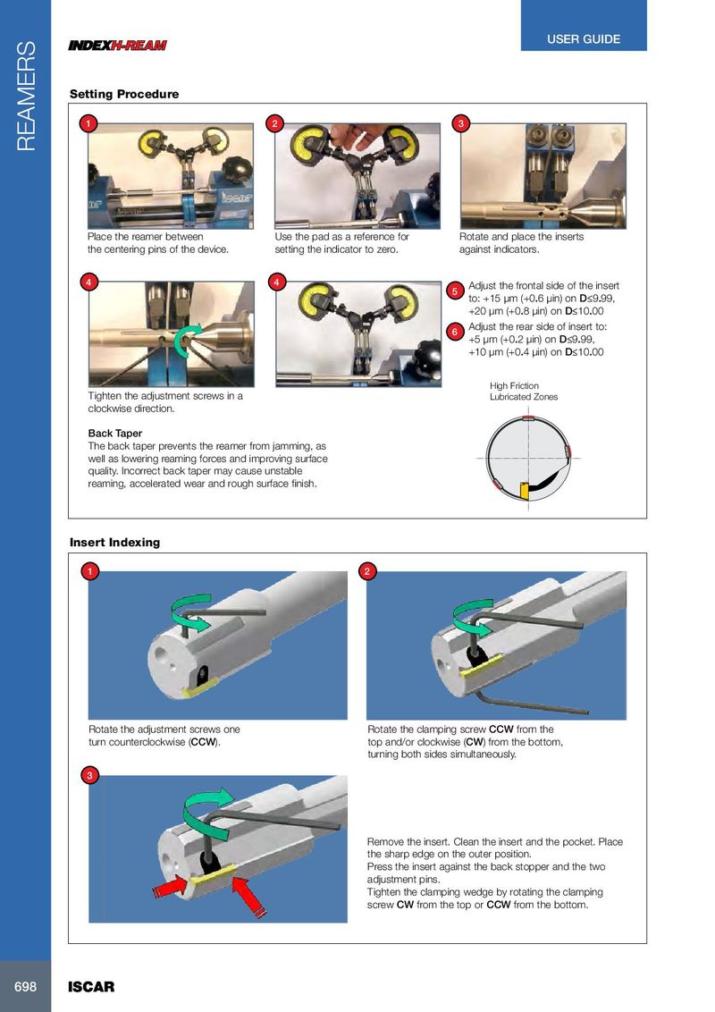
USER GUIDE Setting Procedure 1 2 3 REAMERS Place the reamer between Use the pad as a reference for Rotate and place the inserts the centering pins of the device. setting the indicator to zero. against indicators. 4 4 Adjust the frontal side of the insert 5 to: +15 µm (+0.6 µin) on D≤9.99, +20 µm (+0.8 µin) on D≤10.00 Adjust the rear side of insert to: 6 +5 µm (+0.2 µin) on D≤9.99, +10 µm (+0.4 µin) on D≤10.00 High Friction Tighten the adjustment screws in a Lubricated Zones clockwise direction. Back Taper The back taper prevents the reamer from jamming, as well as lowering reaming forces and improving surface quality. Incorrect back taper may cause unstable reaming, accelerated wear and rough surface finish. Insert Indexing 1 2 Rotate the adjustment screws one Rotate the clamping screw CCW from the turn counterclockwise (CCW). top and/or clockwise (CW) from the bottom, turning both sides simultaneously. 3 Remove the insert. Clean the insert and the pocket. Place the sharp edge on the outer position. Press the insert against the back stopper and the two adjustment pins. Tighten the clamping wedge by rotating the clamping screw CW from the top or CCW from the bottom. 698 698 ISCAR ISCAR