Каталог Iscar вращающийся инструмент 2017 - страница 393
Навигация
 Каталог Iscar токарные пластины ISO 2022
 Каталог Iscar инструмент для фрезерования
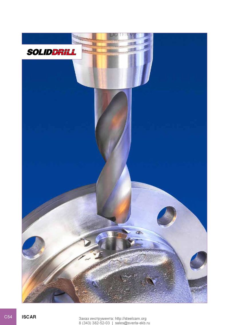 Каталог Iscar решения для глубокого сверления
 Каталог Iscar полирующие фрезы
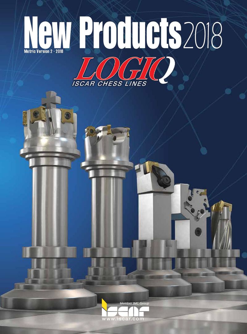 Каталог Iscar новые продукты 2018
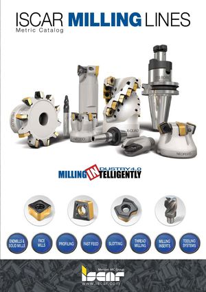 Каталог Iscar концевые фрезы со сменными пластинами 2022
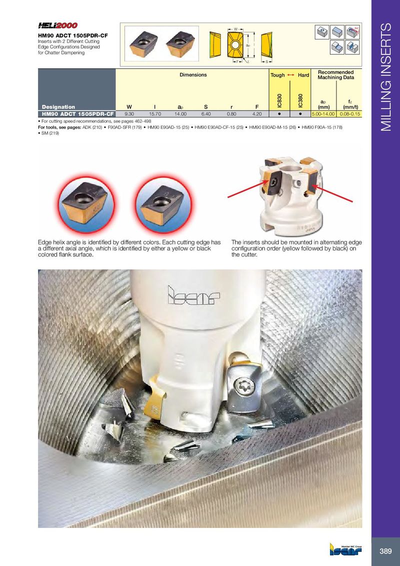
W Rd° HM90 ADCT 1505PDR-CF Inserts with 2 Different Cutting Edge Configurations Designed ap l for Chatter Dampening F r S Recommended Dimensions Tough 1 Hard Machining Data a p f z Designation W l a p S r F IC830 IC380 (mm) (mm/t) HM90 ADCT 1505PDR-CF 9.30 15.70 14.00 6.40 0.80 4.20 • • 5.00-14.00 0.08-0.15 • For cutting speed recommendations, see pages 462-498 For tools, see pages: ADK (210) • F90AD-SFR (179) • HM90 E90AD-15 (25) • HM90 E90AD-CF-15 (25) • HM90 E90AD-M-15 (26) • HM90 F90A-15 (178) MILLING INSERTS • SM (219) Edge helix angle is identified by different colors. Each cutting edge has The inserts should be mounted in alternating edge a different axial angle, which is identified by either a yellow or black configuration order (yellow followed by black) on colored flank surface. the cutter. 389