Каталог Iscar токарный инструмент 2017 - страница 450
Навигация
 Каталог Iscar резьбонарезные фрезы
 Каталог Iscar инструмент для обработки алюминиевых колёс
 Каталог Iscar державки и пластины для нарезания резьбы 2022
 Каталог Iscar расточные системы 2022
 Каталог Iscar высокоточные развертки и метчики 2022
 Каталог Iscar вращающийся инструмент 2017
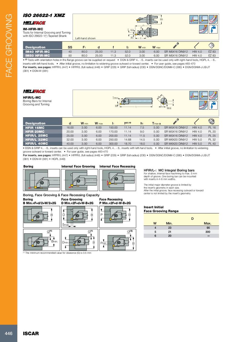
SS F 1 d IM-HFIR-MC f 5.3 Tools for Internal Grooving and Turning with ISO 26622-1(*) Tapered Shank Left-hand shown W l 2 Designation SS F 1 d f l 2 W min W max IM40 HFIR-MC 40 80.0 25.00 11.3 52.0 3.00 6.00 SR M5X16 DIN912 HW 4.0 EZ 83 IM50 HFIR-MC 50 80.0 25.00 11.3 52.0 3.00 6.00 SR M5X16 DIN912 HW 4.0 EZ 83 • (*) Tools with orientation holes in the flange groove can be supplied on request • DGN & GRIP 4.. - 6.. inserts can be used only with right-hand tools, HGPL 4.. - 6.. inserts with left-hand tools. • After initial groove, no limitation to widening groove outward or toward center. • For user guide, see pages 460-470 For inserts, see pages: HFPR/L (447) • HFPR/L (full radius) (448) • GRIP (229) • GRIP (full radius) (230) • DGN/DGNC/DGNM-C (380) • DGN/DGNM-J/JS/JT (381) • DGN-W (381) FACE GROOVING HFIR/L-MC Tmax-a dg7 Boring Bars for Internal f Grooving and Turning W l1 h1 W/2 Designation d W min W max l 1 f ±0.10 h 1 T max- a HFIR 16MC 16.00 3.00 6.00 150.00 11.14 7.5 5.00 SR M5X16 DIN912 HW 4.0 PL 16 HFIR 20MC 20.00 3.00 6.00 170.00 11.14 9.0 5.00 SR M5X16 DIN912 HW 4.0 PL 20 HFIR/L 25MC 25.00 3.00 6.00 200.00 11.14 11.5 5.00 SR M5X16 DIN912 HW 4.0 PL 25 HFIR/L 32MC 32.00 3.00 6.00 250.00 14.68 14.5 5.00 SR M6X20 DIN912 HW 5.0 PL 32 HFIR/L 40MC 40.00 3.00 6.00 300.00 18.70 18.0 5.00 SR M6X20 DIN912 HW 5.0 PL 40 • DGN & GRIP 4.. - 6.. inserts can be used only with right-hand tools, HGPL 4.. - 6.. inserts with left-hand tools. • After initial groove, no limitation to widening groove outward or toward center. • For user guide, see pages 460-470 For inserts, see pages: HFPR/L (447) • HFPR/L (full radius) (448) • GRIP (229) • GRIP (full radius) (230) • DGN/DGNC/DGNM-C (380) • DGN/DGNM-J/JS/JT (381) • DGN-W (381) • HGPL (449) Boring Internal Face Grooving Internal Face Recessing HFIR/L-: MC Integral Boring bars For shallow, internal face machining to max. 5 mm depth of groove. One boring bar can be mounted with inserts in 4-6 mm widths. The initial major diameter groove is limited by the insert’s geometry in each size. After the initial groove, face recessing outward or toward center is not limited by the insert’s geometry. Boring, Face Grooving & Face Recessing Capacity Boring Face Grooving Face Recessing B Min.=F+d/2+W/2+2G D Min.=2F+d+W-B+2G P Min.=2F+d-W-B+2G Insert Initial Face Grooving Range B D B P B D 5max W Min. Max. 4 23 90 (1) G G (1) G (1) 5 21 300 6 20 ∞ Bmin. Dmin. B Pmin. B (1) The minimum recommended value for clearance (G) is 0.5 mm 446 ISCAR