Каталог Iscar токарный инструмент 2017 - страница 446
Навигация
 Каталог Iscar резьбонарезные фрезы
 Каталог Iscar инструмент для обработки алюминиевых колёс
 Каталог Iscar державки и пластины для нарезания резьбы 2022
 Каталог Iscar расточные системы 2022
 Каталог Iscar высокоточные развертки и метчики 2022
 Каталог Iscar вращающийся инструмент 2017
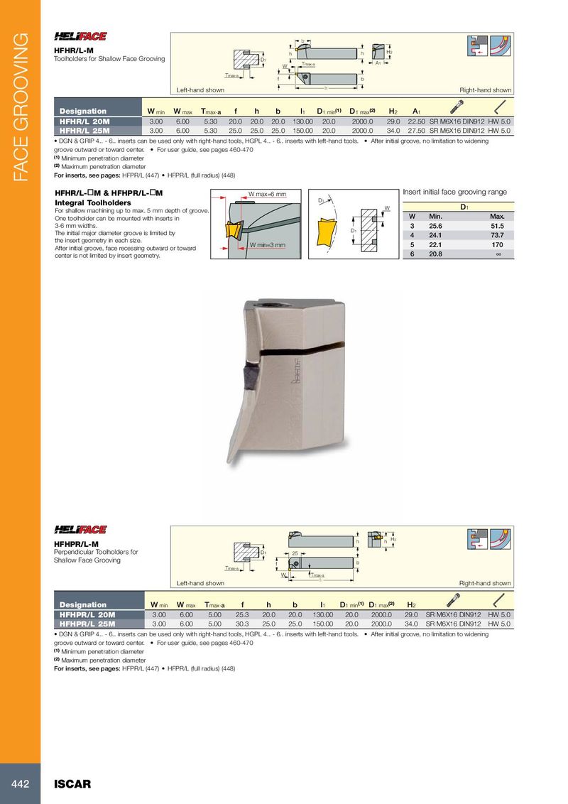
l2 HFHR/L-M h h H2 Toolholders for Shallow Face Grooving D 1 Tmax-a A1 W Tmax-a f b Left-hand shown l1 Right-hand shown Designation W min W max T max- a f h b l 1 D 1 min (1) D 1 max (2) H 2 A 1 HFHR/L 20M 3.00 6.00 5.30 20.0 20.0 20.0 130.00 20.0 2000.0 29.0 22.50 SR M6X16 DIN912 HW 5.0 HFHR/L 25M 3.00 6.00 5.30 25.0 25.0 25.0 150.00 20.0 2000.0 34.0 27.50 SR M6X16 DIN912 HW 5.0 • DGN & GRIP 4.. - 6.. inserts can be used only with right-hand tools, HGPL 4.. - 6.. inserts with left-hand tools. • After initial groove, no limitation to widening groove outward or toward center. • For user guide, see pages 460-470 (1) Minimum penetration diameter (2) Maximum penetration diameter For inserts, see pages: HFPR/L (447) • HFPR/L (full radius) (448) FACE GROOVING HFHR/L- ¨ M & HFHPR/L- ¨ M W max=6 mm Insert initial face grooving range D1 Integral Toolholders W D 1 For shallow machining up to max. 5 mm depth of groove. One toolholder can be mounted with inserts in W Min. Max. 3-6 mm widths. 3 25.6 51.5 The initial major diameter groove is limited by D1 4 24.1 73.7 the insert geometry in each size. W min=3 mm 5 22.1 170 After initial groove, face recessing outward or toward 6 20.8 ∞ center is not limited by insert geometry. h h H2 HFHPR/L-M Perpendicular Toolholders for D 1 25 Shallow Face Grooving f b Tmax-a W Tmax-a l1 Left-hand shown Right-hand shown Designation W min W max T max- a f h b l 1 D 1 min (1) D 1 max (2) H 2 HFHPR/L 20M 3.00 6.00 5.00 25.3 20.0 20.0 130.00 20.0 2000.0 29.0 SR M6X16 DIN912 HW 5.0 HFHPR/L 25M 3.00 6.00 5.00 30.3 25.0 25.0 150.00 20.0 2000.0 34.0 SR M6X16 DIN912 HW 5.0 • DGN & GRIP 4.. - 6.. inserts can be used only with right-hand tools, HGPL 4.. - 6.. inserts with left-hand tools. • After initial groove, no limitation to widening groove outward or toward center. • For user guide, see pages 460-470 (1) Minimum penetration diameter (2) Maximum penetration diameter For inserts, see pages: HFPR/L (447) • HFPR/L (full radius) (448) 442 ISCAR