Каталог Iscar токарный инструмент 2017 - страница 365
Навигация
 Каталог Iscar резьбонарезные фрезы
 Каталог Iscar инструмент для обработки алюминиевых колёс
 Каталог Iscar державки и пластины для нарезания резьбы 2022
 Каталог Iscar расточные системы 2022
 Каталог Iscar высокоточные развертки и метчики 2022
 Каталог Iscar вращающийся инструмент 2017
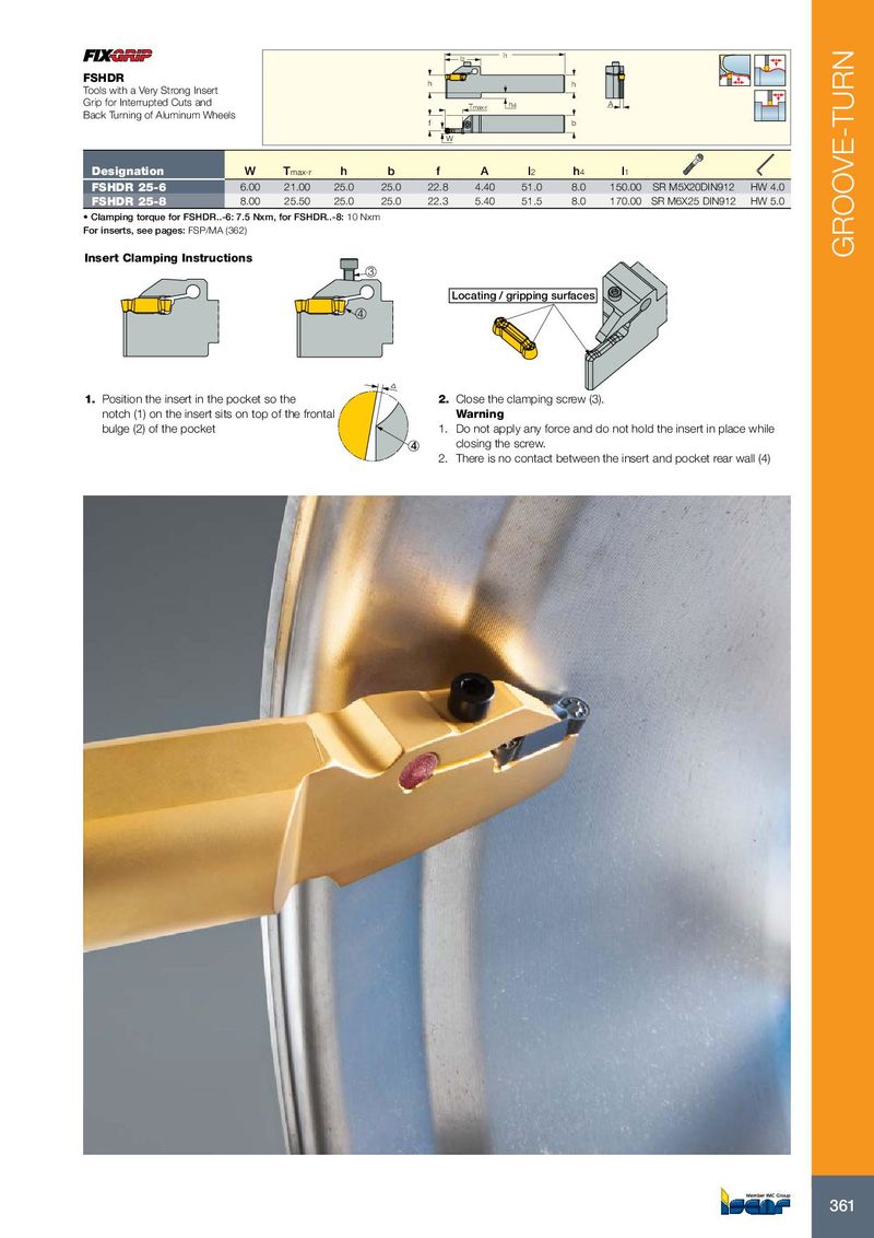
l2 l1 FSHDR h h Tools with a Very Strong Insert Grip for Interrupted Cuts and Tmax-r h4 A Back Turning of Aluminum Wheels f b W Designation W T max-r h b f A l 2 h 4 l 1 FSHDR 25-6 6.00 21.00 25.0 25.0 22.8 4.40 51.0 8.0 150.00 SR M5X20DIN912 HW 4.0 FSHDR 25-8 8.00 25.50 25.0 25.0 22.3 5.40 51.5 8.0 170.00 SR M6X25 DIN912 HW 5.0 • Clamping torque for FSHDR..-6: 7.5 Nxm, for FSHDR..-8: 10 Nxm For inserts, see pages: FSP/MA (362) Insert Clamping Instructions GROOVE-TURN 3 Locating / gripping surfaces 4 1. Position the insert in the pocket so the 2. Close the clamping screw (3). notch (1) on the insert sits on top of the frontal Warning bulge (2) of the pocket 1. Do not apply any force and do not hold the insert in place while 4 closing the screw. 2. There is no contact between the insert and pocket rear wall (4) 361