Каталог Iscar токарный инструмент 2017 - страница 353
Навигация
 Каталог Iscar резьбонарезные фрезы
 Каталог Iscar инструмент для обработки алюминиевых колёс
 Каталог Iscar державки и пластины для нарезания резьбы 2022
 Каталог Iscar расточные системы 2022
 Каталог Iscar высокоточные развертки и метчики 2022
 Каталог Iscar вращающийся инструмент 2017
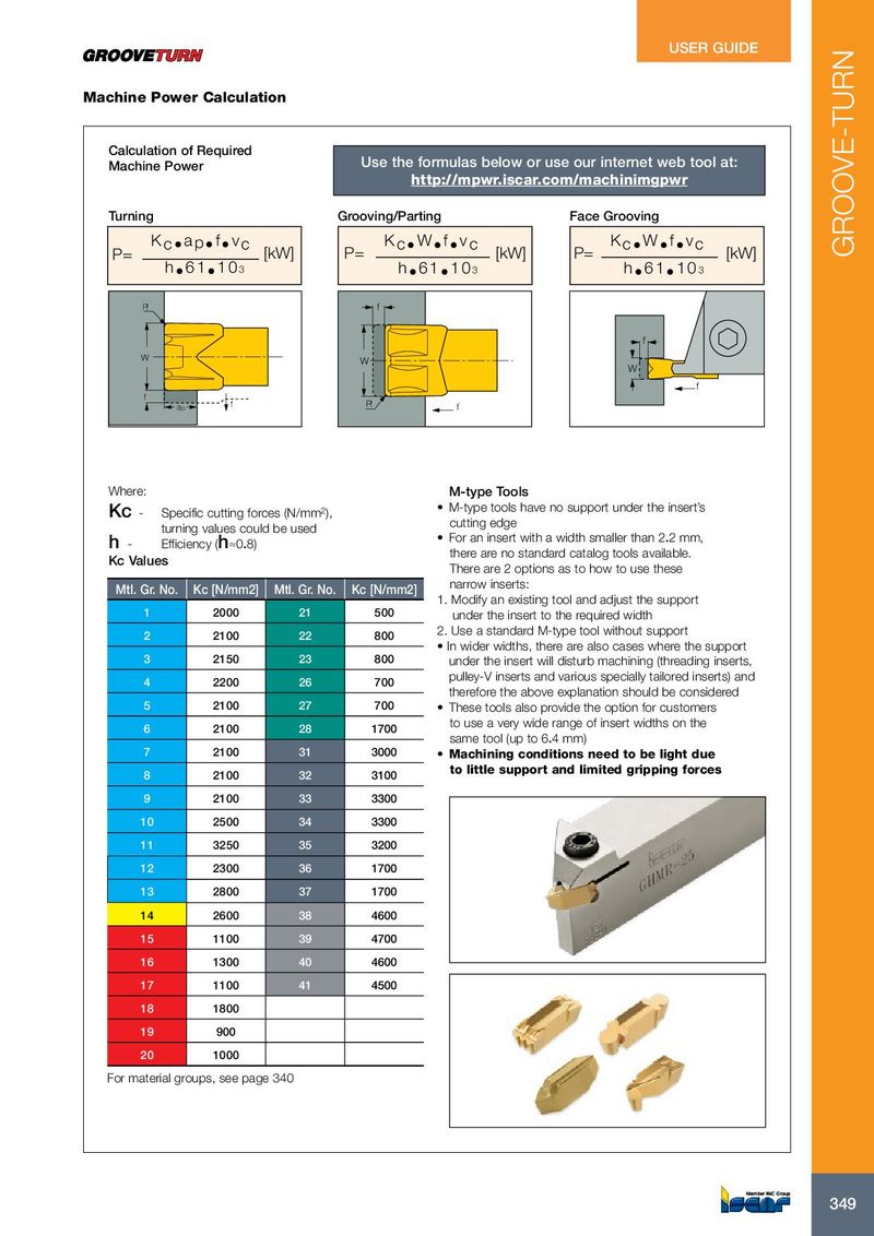
USER GUIDE Machine Power Calculation Calculation of Required Machine Power Use the formulas below or use our internet web tool at: http://mpwr.iscar.com/machinimgpwr Turning Grooving/Parting Face Grooving K c • a p • f • v c K c • W • f • v c K c • W • f • v c P= [kW] P= [kW] P= [kW] GROOVE-TURN h • 6 1 • 1 0 3 h • 6 1 • 1 0 3 h • 6 1 • 1 0 3 R f f W W W f f ap f R f Where: M-type Tools • M-type tools have no support under the insert’s Kc - Specific cutting forces (N/mm 2 ), cutting edge turning values could be used • For an insert with a width smaller than 2.2 mm, h - Efficiency (h≈0.8) there are no standard catalog tools available. Kc Values There are 2 options as to how to use these narrow inserts: Mtl. Gr. No. Kc [N/mm2] Mtl. Gr. No. Kc [N/mm2] 1. Modify an existing tool and adjust the support 1 2000 21 500 under the insert to the required width 2. Use a standard M-type tool without support 2 2100 22 800 • In wider widths, there are also cases where the support 3 2150 23 800 under the insert will disturb machining (threading inserts, pulley-V inserts and various specially tailored inserts) and 4 2200 26 700 therefore the above explanation should be considered 5 2100 27 700 • These tools also provide the option for customers to use a very wide range of insert widths on the 6 2100 28 1700 same tool (up to 6.4 mm) 7 2100 31 3000 • Machining conditions need to be light due to little support and limited gripping forces 8 2100 32 3100 9 2100 33 3300 10 2500 34 3300 11 3250 35 3200 12 2300 36 1700 13 2800 37 1700 14 2600 38 4600 15 1100 39 4700 16 1300 40 4600 17 1100 41 4500 18 1800 19 900 20 1000 For material groups, see page 340 349 349