Каталог Iscar токарный инструмент 2017 - страница 350
Навигация
 Каталог Iscar резьбонарезные фрезы
 Каталог Iscar инструмент для обработки алюминиевых колёс
 Каталог Iscar державки и пластины для нарезания резьбы 2022
 Каталог Iscar расточные системы 2022
 Каталог Iscar высокоточные развертки и метчики 2022
 Каталог Iscar вращающийся инструмент 2017
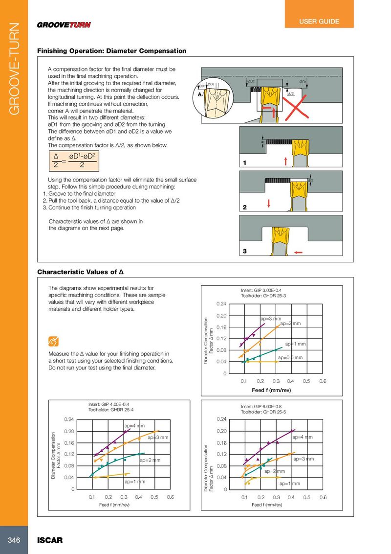
USER GUIDE Finishing Operation: Diameter Compensation A compensation factor for the final diameter must be used in the final machining operation. ØD 2 After the initial grooving to the required final diameter, ØD 1 ØD1 ØD2 the machining direction is normally changed for A Δ/2 longitudinal turning. At this point the deflection occurs. If machining continues without correction, corner A will penetrate the material. GROOVE-TURN This will result in two different diameters: øD1 from the grooving and øD2 from the turning. The difference between øD1 and øD2 is a value we define as ∆. a p The compensation factor is ∆/2, as shown below. 1 2 ∆ øD -øD = 1 2 2 Using the compensation factor will eliminate the small surface Δ/2 step. Follow this simple procedure during machining: 1. Groove to the final diameter 2. Pull the tool back, a distance equal to the value of ∆/2 3. Continue the finish turning operation 2 Characteristic values of ∆ are shown in the diagrams on the next page. 3 Characteristic Values of ∆ The diagrams show experimental results for Insert: GIP 3.00E-0.4 specific machining conditions. These are sample Toolholder: GHDR 25-3 values that will vary with different workpiece 0.24 materials and different holder types. 0.20 ap=3 mm ap=2 mm 0.16 0.12 ap=1 mm Factor ∆ mm 0.08 Measure the ∆ value for your finishing operation in ap=0.5 mm a short test using your selected finishing conditions. Diameter Compensation 0.04 Do not run your test using the final diameter. 0 0.1 0.2 0.3 0.4 0.5 0.6 Feed f (mm/rev) Insert: GIP 4.00E-0.4 Insert: GIP 6.00E-0.8 Toolholder: GHDR 25-4 Toolholder: GHDR 25-5 0.24 0.24 ap=4 mm 0.20 0.20 ap=3 mm ap=4 mm 0.16 0.16 0.12 0.12 ap=2 mm ap=3 mm Factor ∆ mm 0.08 0.08 ap=2 mm Diameter Compensation 0.04 0.04 ap=1 mm ap=1 mm 0 Diameter Compensation Factor ∆ mm 0 0.1 0.2 0.3 0.4 0.5 0.6 0.1 0.2 0.3 0.4 0.5 0.6 Feed f (mm/rev) Feed f (mm/rev) 346 346 ISCAR ISCAR