Каталог Iscar токарный инструмент 2017 - страница 316
Навигация
 Каталог Iscar резьбонарезные фрезы
 Каталог Iscar инструмент для обработки алюминиевых колёс
 Каталог Iscar державки и пластины для нарезания резьбы 2022
 Каталог Iscar расточные системы 2022
 Каталог Iscar высокоточные развертки и метчики 2022
 Каталог Iscar вращающийся инструмент 2017
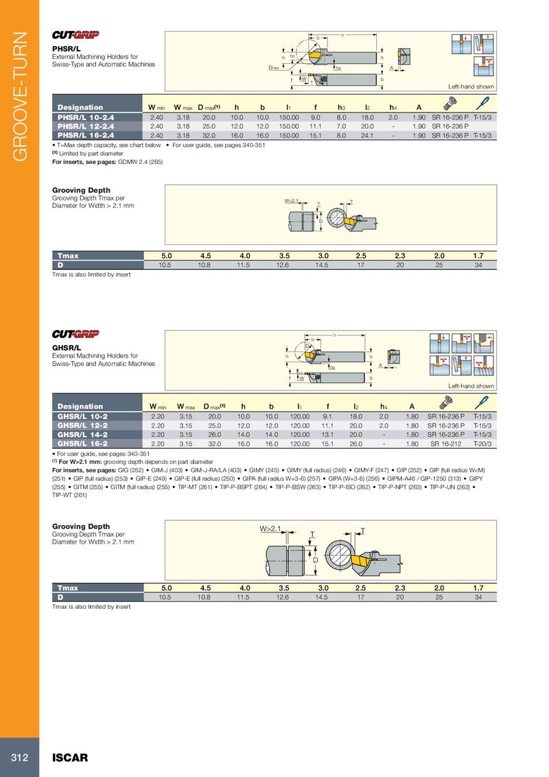
l1
l2
PHSR/L
External Machining Holders for h h3 h
Swiss-Type and Automatic Machines Dmax h4 A
f W b
T
Left-hand shown
Designation W min W max D max (1) h b l 1 f h 3 l 2 h 4 A
PHSR/L 10-2.4 2.40 3.18 20.0 10.0 10.0 150.00 9.0 8.0 18.0 2.0 1.90 SR 16-236 P T-15/3
PHSR/L 12-2.4 2.40 3.18 25.0 12.0 12.0 150.00 11.1 7.0 20.0 - 1.90 SR 16-236 P
PHSR/L 16-2.4 2.40 3.18 32.0 16.0 16.0 150.00 15.1 8.0 24.1 - 1.90 SR 16-236 P T-15/3
• T=Max depth capacity, see chart below • For user guide, see pages 340-351
(1) Limited by part diameter
GROOVE-TURN For inserts, see pages: GDMW 2.4 (265)
Grooving Depth
Grooving Depth Tmax per W>2.1
Diameter for Width > 2.1 mm T T
D
Tmax 5.0 4.5 4.0 3.5 3.0 2.5 2.3 2.0 1.7
D 10.5 10.8 11.5 12.6 14.5 17 20 25 34
Tmax is also limited by insert
l1
l2
D
GHSR/L
External Machining Holders for h h
Swiss-Type and Automatic Machines
h4 A
f W b
Left-hand shown
Designation W min W max D max (1) h b l 1 f l 2 h 4 A
GHSR/L 10-2 2.20 3.15 20.0 10.0 10.0 120.00 9.1 18.0 2.0 1.80 SR 16-236 P T-15/3
GHSR/L 12-2 2.20 3.15 25.0 12.0 12.0 120.00 11.1 20.0 2.0 1.80 SR 16-236 P T-15/3
GHSR/L 14-2 2.20 3.15 26.0 14.0 14.0 120.00 13.1 20.0 - 1.80 SR 16-236 P T-15/3
GHSR/L 16-2 2.20 3.15 32.0 16.0 16.0 120.00 15.1 26.0 - 1.80 SR 16-212 T-20/3
• For user guide, see pages 340-351
(1) For W>2.1 mm: grooving depth depends on part diameter
For inserts, see pages: GIG (252) • GIM-J (403) • GIM-J-RA/LA (403) • GIMY (245) • GIMY (full radius) (246) • GIMY-F (247) • GIP (252) • GIP (full radius W