Каталог Iscar токарный инструмент 2017 - страница 306
Навигация
 Каталог Iscar резьбонарезные фрезы
 Каталог Iscar инструмент для обработки алюминиевых колёс
 Каталог Iscar державки и пластины для нарезания резьбы 2022
 Каталог Iscar расточные системы 2022
 Каталог Iscar высокоточные развертки и метчики 2022
 Каталог Iscar вращающийся инструмент 2017
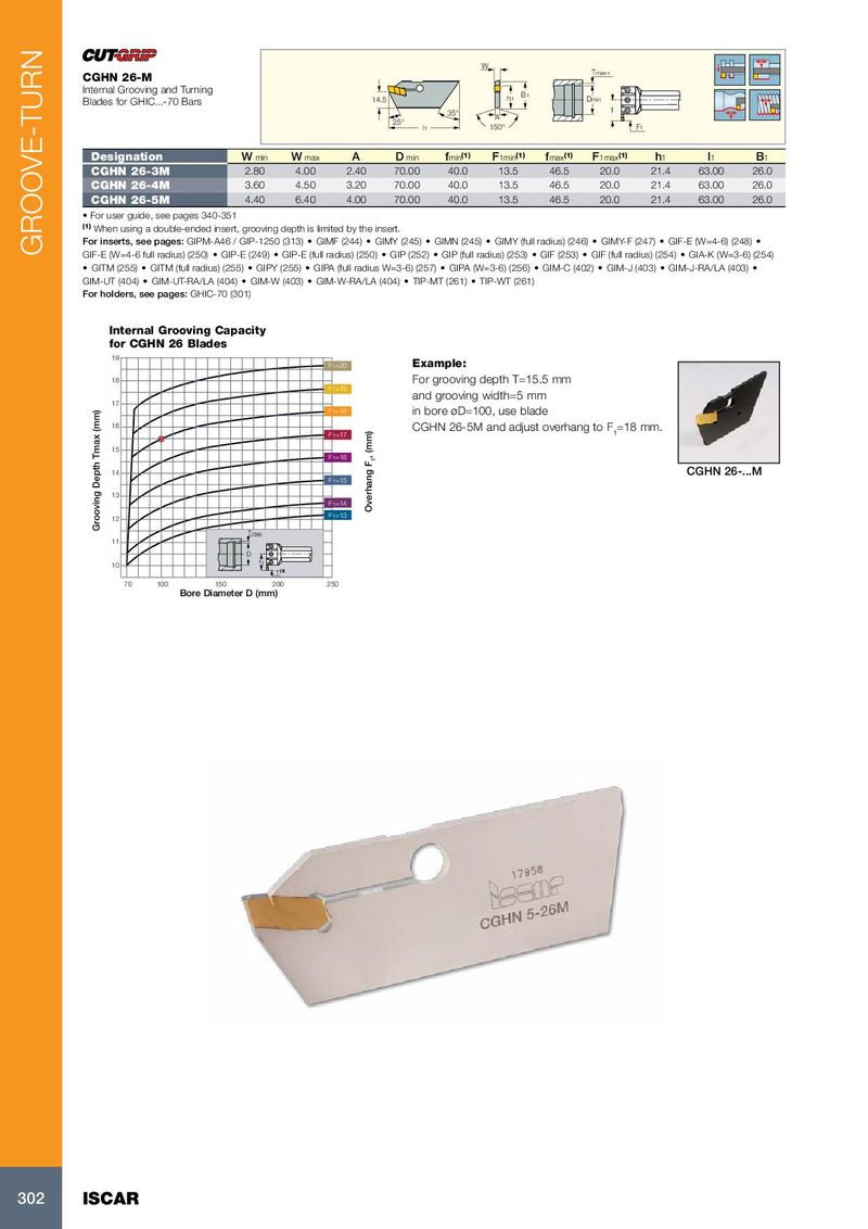
W Tmax-r CGHN 26-M Internal Grooving and Turning Blades for GHIC...-70 Bars 14.5 h1 B1 Dmin 35° f A 25° l1 150° F1 Designation W min W max A D min f min (1) F 1min (1) f max (1) F 1max (1) h 1 l 1 B 1 CGHN 26-3M 2.80 4.00 2.40 70.00 40.0 13.5 46.5 20.0 21.4 63.00 26.0 CGHN 26-4M 3.60 4.50 3.20 70.00 40.0 13.5 46.5 20.0 21.4 63.00 26.0 CGHN 26-5M 4.40 6.40 4.00 70.00 40.0 13.5 46.5 20.0 21.4 63.00 26.0 • For user guide, see pages 340-351 (1) When using a double-ended insert, grooving depth is limited by the insert. For inserts, see pages: GIPM-A46 / GIP-1250 (313) • GIMF (244) • GIMY (245) • GIMN (245) • GIMY (full radius) (246) • GIMY-F (247) • GIF-E (W=4-6) (248) • GROOVE-TURN GIF-E (W=4-6 full radius) (250) • GIP-E (249) • GIP-E (full radius) (250) • GIP (252) • GIP (full radius) (253) • GIF (253) • GIF (full radius) (254) • GIA-K (W=3-6) (254) • GITM (255) • GITM (full radius) (255) • GIPY (255) • GIPA (full radius W=3-6) (257) • GIPA (W=3-6) (256) • GIM-C (402) • GIM-J (403) • GIM-J-RA/LA (403) • GIM-UT (404) • GIM-UT-RA/LA (404) • GIM-W (403) • GIM-W-RA/LA (404) • TIP-MT (261) • TIP-WT (261) For holders, see pages: GHIC-70 (301) Internal Grooving Capacity for CGHN 26 Blades 19 F1=20 Example: 18 For grooving depth T=15.5 mm F1=19 and grooving width=5 mm 17 F1=18 in bore øD=100, use blade 16 CGHN 26-5M and adjust overhang to F F1=17 1 =18 mm. 15 F1=16 , (mm) 1 14 CGHN 26-...M F1=15 13 F1=14 Overhang F 12 F1=13 Grooving Depth Tmax (mm) Tmax 11 D 10 f1 T (1) 70 100 150 200 250 Bore Diameter D (mm) 302 ISCAR