Каталог Iscar токарный инструмент 2017 - страница 304
Навигация
 Каталог Iscar резьбонарезные фрезы
 Каталог Iscar инструмент для обработки алюминиевых колёс
 Каталог Iscar державки и пластины для нарезания резьбы 2022
 Каталог Iscar расточные системы 2022
 Каталог Iscar высокоточные развертки и метчики 2022
 Каталог Iscar вращающийся инструмент 2017
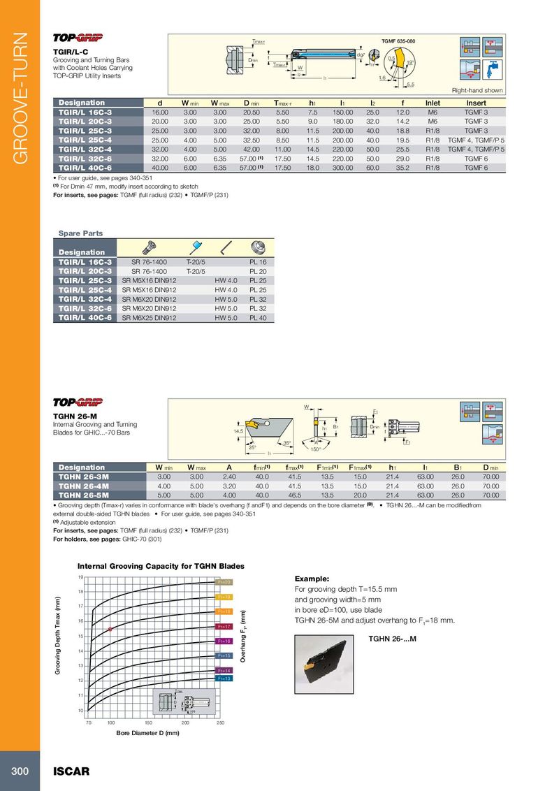
Tmax-r TGMF 635-080 TGIR/L-C dg 7 Grooving and Turning Bars Dmin f 0.5 Tmax-r h 1 19° with Coolant Holes Carrying W TOP-GRIP Utility Inserts l 2 l 1 1.6 5.5 Right-hand shown Designation d W min W max D min T max-r h 1 l 1 l 2 f Inlet Insert TGIR/L 16C-3 16.00 3.00 3.00 20.50 5.50 7.5 150.00 25.0 12.0 M6 TGMF 3 TGIR/L 20C-3 20.00 3.00 3.00 25.00 5.50 9.0 180.00 32.0 14.2 M6 TGMF 3 TGIR/L 25C-3 25.00 3.00 3.00 32.00 8.00 11.5 200.00 40.0 18.8 R1/8 TGMF 3 TGIR/L 25C-4 25.00 4.00 5.00 32.50 8.50 11.5 200.00 40.0 19.5 R1/8 TGMF 4, TGMF/P 5 TGIR/L 32C-4 32.00 4.00 5.00 42.00 11.00 14.5 220.00 50.0 25.5 R1/8 TGMF 4, TGMF/P 5 TGIR/L 32C-6 32.00 6.00 6.35 57.00 (1) 17.50 14.5 220.00 50.0 29.0 R1/8 TGMF 6 GROOVE-TURN TGIR/L 40C-6 40.00 6.00 6.35 57.00 (1) 17.50 18.0 300.00 60.0 35.2 R1/8 TGMF 6 • For user guide, see pages 340-351 (1) For Dmin 47 mm, modify insert according to sketch For inserts, see pages: TGMF (full radius) (232) • TGMF/P (231) Spare Parts Designation TGIR/L 16C-3 SR 76-1400 T-20/5 PL 16 TGIR/L 20C-3 SR 76-1400 T-20/5 PL 20 TGIR/L 25C-3 SR M5X16 DIN912 HW 4.0 PL 25 TGIR/L 25C-4 SR M5X16 DIN912 HW 4.0 PL 25 TGIR/L 32C-4 SR M6X20 DIN912 HW 5.0 PL 32 TGIR/L 32C-6 SR M6X20 DIN912 HW 5.0 PL 32 TGIR/L 40C-6 SR M6X25 DIN912 HW 5.0 PL 40 W F1 TGHN 26-M Internal Grooving and Turning h1 B1 Dmin Blades for GHIC...-70 Bars 14.5 f 35° A F1 25° 150° l1 Designation W min W max A f min (1) f max (1) F 1min (1) F 1max (1) h 1 l 1 B 1 D min TGHN 26-3M 3.00 3.00 2.40 40.0 41.5 13.5 15.0 21.4 63.00 26.0 70.00 TGHN 26-4M 4.00 5.00 3.20 40.0 41.5 13.5 15.0 21.4 63.00 26.0 70.00 TGHN 26-5M 5.00 5.00 4.00 40.0 46.5 13.5 20.0 21.4 63.00 26.0 70.00 • Grooving depth (Tmax-r) varies in conformance with blade's overhang (f andF1) and depends on the bore diameter (D) . • TGHN 26...-M can be modifiedfrom external double-sided TGHN blades • For user guide, see pages 340-351 (1) Adjustable extension For inserts, see pages: TGMF (full radius) (232) • TGMF/P (231) For holders, see pages: GHIC-70 (301) Internal Grooving Capacity for TGHN Blades 19 F1=20 Example: 18 For grooving depth T=15.5 mm F1=19 and grooving width=5 mm 17 F1=18 in bore øD=100, use blade 16 TGHN 26-5M and adjust overhang to F F1=17 , (mm) 1 =18 mm. 1 15 F1=16 TGHN 26-...M 14 F1=15 Overhang F 13 Grooving Depth Tmax (mm) F1=14 12 F1=13 Tmax 11 D f1 10 T (1) 70 100 150 200 250 Bore Diameter D (mm) 300 ISCAR