Каталог Iscar токарный инструмент 2017 - страница 262
Навигация
 Каталог Iscar резьбонарезные фрезы
 Каталог Iscar инструмент для обработки алюминиевых колёс
 Каталог Iscar державки и пластины для нарезания резьбы 2022
 Каталог Iscar расточные системы 2022
 Каталог Iscar высокоточные развертки и метчики 2022
 Каталог Iscar вращающийся инструмент 2017
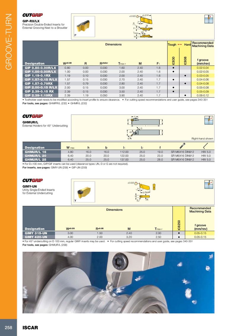
±0.025 15.3 Ref GIP-RX/LX 7° R Precision Double-Ended Inserts for M External Grooving Next to a Shoulder F1 Tmax-r 25° W Recommended Dimensions Tough 1 Hard Machining Data f groove Designation W ±0.02 R R ±toler T max-r M F 1 IC830 IC808 (mm/rev) GROOVE-TURN GIP 0.80-0.00R/LX 0.80 0.00 0.030 1.60 2.40 1.6 • 0.02-0.04 GIP 1.00-0.00R/LX 1.00 0.00 0.030 2.00 2.40 1.6 • 0.02-0.05 GIP 1.19-0.1RX 1.19 0.10 0.030 2.00 2.40 1.6 • 0.03-0.05 GIP 1.57-0.15 R/LX 1.57 0.15 0.030 2.70 2.40 1.7 • 0.04-0.06 GIP 1.57-0.79RX 1.57 0.79 0.030 2.80 2.40 1.7 • 0.04-0.08 GIP 2.00-0.15 R/LX 2.00 0.15 0.030 3.00 2.40 1.7 • 0.05-0.08 GIP 2.39-0.15 RX 2.39 0.15 0.030 3.50 2.40 1.7 • 0.05-0.09 GIP 2.39-1.19RX 2.39 1.19 0.050 3.90 2.40 1.7 • 0.06-0.12 • Toolholder seat needs to be modified according to insert profile to ensure clearance. • For cutting speed recommendations and user guide, see pages 340-351 For tools, see pages: GHMPR/L (232) • GHMR/L (232) l2 GHMUR/L h h External Holders for 45° Undercutting l1 1.5 f 45° b W Right-hand shown Designation W max h b l 1 l 2 f GHMUR/L 16 4.80 16.0 16.0 112.00 25.0 19.0 SR M6X16 DIN912 HW 5.0 GHMUR/L 20 6.40 20.0 20.0 122.00 25.0 23.0 SR M6X16 DIN912 HW 5.0 GHMUR/L 25 6.40 25.0 25.0 137.00 25.0 28.0 SR M6X16 DIN912 HW 5.0 • For D>100 mm, GIP/GIF inserts can be used (clearance types UN, D or G are not required). For inserts, see pages: GIMY-UN (258) • GIP-UN (259) ±0.025 GIMY-UN Utility Single-Ended Inserts 7° for External Undercutting 15 Ref. W M R Recommended Dimensions Machining Data f groove Designation W ±0.05 R ±0.05 M T max-r IC8250 (mm/rev) GIMY 315-UN 3.00 1.50 2.40 2.00 • 0.05-0.15 GIMY 420-UN 4.00 2.00 3.20 2.50 • 0.05-0.15 • For 45° undercutting on D 100 mm, regular GIMY inserts may be used. • For cutting speed recommendations and user guide, see pages 340-351 For tools, see pages: GHMUR/L (258) 258 ISCAR