Каталог Iscar токарный инструмент 2017 - страница 263
Навигация
 Каталог Iscar резьбонарезные фрезы
 Каталог Iscar инструмент для обработки алюминиевых колёс
 Каталог Iscar державки и пластины для нарезания резьбы 2022
 Каталог Iscar расточные системы 2022
 Каталог Iscar высокоточные развертки и метчики 2022
 Каталог Iscar вращающийся инструмент 2017
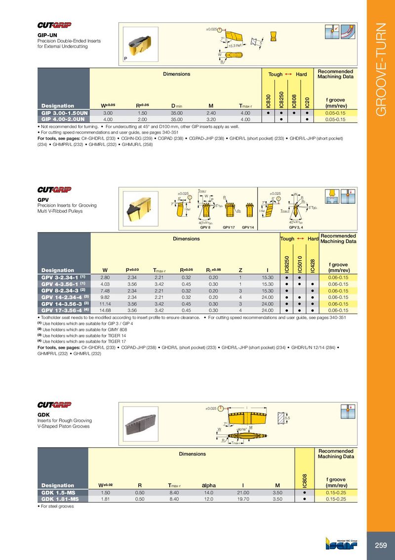
±0.025 GIP-UN 7° Precision Double-Ended Inserts 5 for External Undercutting 15.3 Ref. W R Recommended Dimensions Tough 1 Hard Machining Data f groove Designation W ±0.05 R ±0.05 D min M T max-r IC830 IC8250 IC808 IC20 (mm/rev) GIP 3.00-1.50UN 3.00 1.50 35.00 2.40 4.00 • • • • 0.05-0.15 GROOVE-TURN GIP 4.00-2.0UN 4.00 2.00 35.00 3.20 4.00 • • 0.05-0.15 • Not recommended for turning. • For undercutting at 45° and D100 mm, other GIP inserts apply as well. • For cutting speed recommendations and user guide, see pages 340-351 For tools, see pages: C#-GHDR/L (233) • CGHN-DG (239) • CGPAD (238) • CGPAD-JHP (238) • GHDR/L (short pocket) (233) • GHDR/L-JHP (short pocket) (234) • GHMPR/L (232) • GHMR/L (232) • GHMUR/L (258) Tmax-r ±0.025 ±0.025 W W GPV 5˚ R P 5˚ R R 1 Precision Inserts for Grooving 7˚ 7˚ 5˚ Typ. l Ref 5˚ Typ. Multi V-Ribbed Pulleys R 1 l Ref Tmax-r 40˚ ±30´ Typ. 40˚ ±30´ Typ GPV 8 GPV 17 GPV 14 GPV 3, 4 Recommended Dimensions Tough 1 Hard Machining Data f groove Designation W P ±0.03 T max-r R ±0.05 R 1 ±0.05 Z l IC8250 IC5010 IC428 (mm/rev) GPV 3-2.34-1 (1) 2.80 2.34 2.21 0.32 0.20 1 15.30 • • 0.06-0.15 GPV 4-3.56-1 (1) 4.03 3.56 3.42 0.45 0.30 1 15.30 • • • 0.06-0.15 GPV 8-2.34-3 (2) 7.48 2.34 2.21 0.32 0.20 3 15.30 • • 0.06-0.15 GPV 14-2.34-4 (3) 9.82 2.34 2.21 0.32 0.20 4 24.00 • • • 0.06-0.15 GPV 14-3.56-3 (3) 11.14 3.56 3.42 0.45 0.30 3 24.00 • • • 0.06-0.15 GPV 17-3.56-4 (4) 14.68 3.56 3.42 0.45 0.30 4 24.00 • • • 0.06-0.15 • Toolholder seat needs to be modified according to insert profile to ensure clearance. • For cutting speed recommendations and user guide, see pages 340-351 (1) Use holders which are suitable for GIP 3 / GIP 4 (2) Use holders which are suitable for GIMY 808 (3) Use holders which are suitable for TIGER 14 (4) Use holders which are suitable for TIGER 17 For tools, see pages: C#-GHDR/L (233) • CGPAD-JHP (238) • GHDR/L (short pocket) (233) • GHDR/L-JHP (short pocket) (234) • GHDR/L/N 12/14 (284) • GHMPR/L (232) • GHMR/L (232) ±0.025 l GDK 5.5 Inserts for Rough Grooving 7° V-Shaped Piston Grooves W alpha° M R Tmax-r Recommended Dimensions Machining Data f groove Designation W ±0.02 R T max-r alpha l M IC808 (mm/rev) GDK 1.5-MS 1.50 0.50 8.40 14.0 21.00 3.50 • 0.15-0.25 GDK 1.81-MS 1.81 0.50 8.40 12.0 19.70 3.50 • 0.15-0.25 • For steel grooves 259