Каталог Iscar токарный инструмент 2017 - страница 236
Навигация
 Каталог Iscar резьбонарезные фрезы
 Каталог Iscar инструмент для обработки алюминиевых колёс
 Каталог Iscar державки и пластины для нарезания резьбы 2022
 Каталог Iscar расточные системы 2022
 Каталог Iscar высокоточные развертки и метчики 2022
 Каталог Iscar вращающийся инструмент 2017
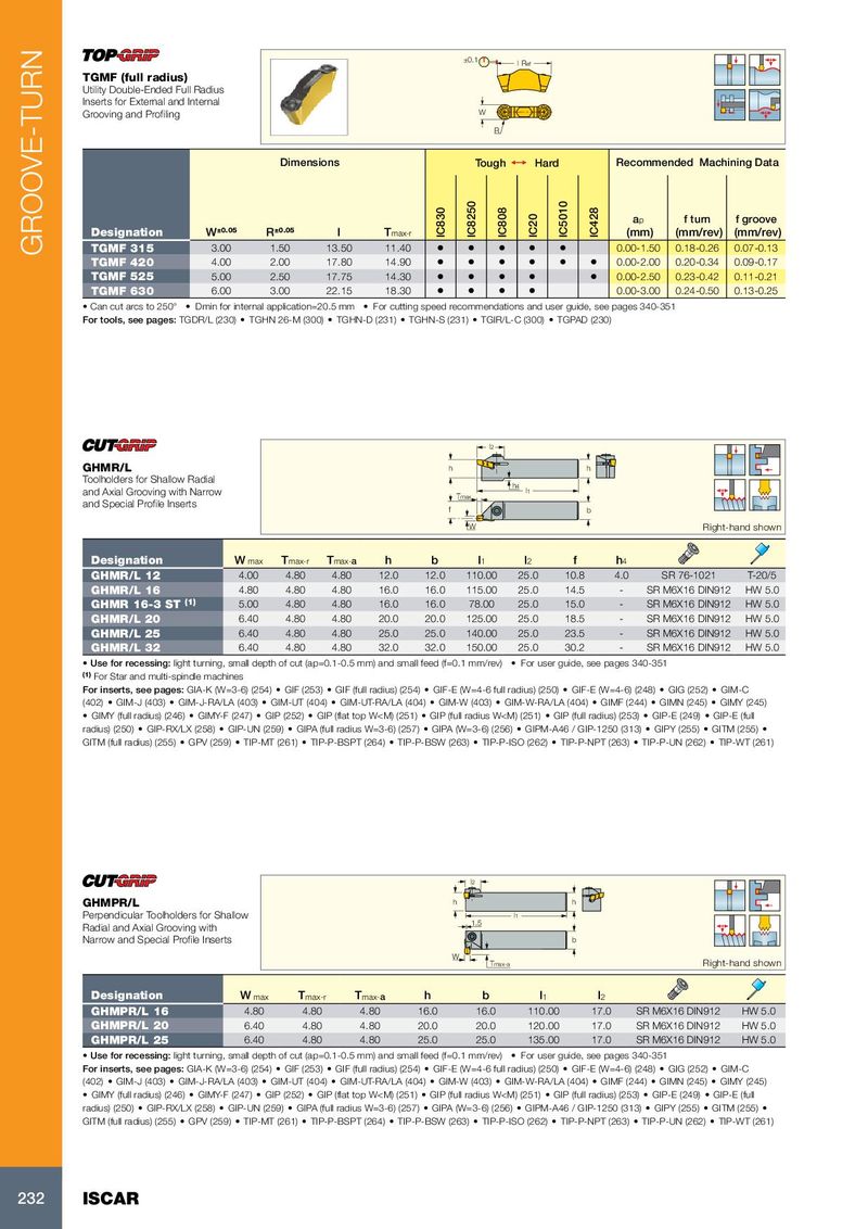
±0.1 l Ref
TGMF (full radius)
Utility Double-Ended Full Radius
Inserts for External and Internal
Grooving and Profiling W
R
Dimensions Tough 1 Hard Recommended Machining Data
a p f turn f groove
Designation W ±0.05 R ±0.05 l T max-r IC830 IC8250 IC808 IC20 IC5010 IC428 (mm) (mm/rev) (mm/rev)
GROOVE-TURN TGMF 315 3.00 1.50 13.50 11.40 • • • • • 0.00-1.50 0.18-0.26 0.07-0.13
TGMF 420 4.00 2.00 17.80 14.90 • • • • • • 0.00-2.00 0.20-0.34 0.09-0.17
TGMF 525 5.00 2.50 17.75 14.30 • • • • • 0.00-2.50 0.23-0.42 0.11-0.21
TGMF 630 6.00 3.00 22.15 18.30 • • • • 0.00-3.00 0.24-0.50 0.13-0.25
• Can cut arcs to 250° • Dmin for internal application=20.5 mm • For cutting speed recommendations and user guide, see pages 340-351
For tools, see pages: TGDR/L (230) • TGHN 26-M (300) • TGHN-D (231) • TGHN-S (231) • TGIR/L-C (300) • TGPAD (230)
l2
GHMR/L h h
Toolholders for Shallow Radial
h4
and Axial Grooving with Narrow l1
Tmax
and Special Profile Inserts
f b
W Right-hand shown
Designation W max T max-r T max- a h b l 1 l 2 f h 4
GHMR/L 12 4.00 4.80 4.80 12.0 12.0 110.00 25.0 10.8 4.0 SR 76-1021 T-20/5
GHMR/L 16 4.80 4.80 4.80 16.0 16.0 115.00 25.0 14.5 - SR M6X16 DIN912 HW 5.0
GHMR 16-3 ST (1) 5.00 4.80 4.80 16.0 16.0 78.00 25.0 15.0 - SR M6X16 DIN912 HW 5.0
GHMR/L 20 6.40 4.80 4.80 20.0 20.0 125.00 25.0 18.5 - SR M6X16 DIN912 HW 5.0
GHMR/L 25 6.40 4.80 4.80 25.0 25.0 140.00 25.0 23.5 - SR M6X16 DIN912 HW 5.0
GHMR/L 32 6.40 4.80 4.80 32.0 32.0 150.00 25.0 30.2 - SR M6X16 DIN912 HW 5.0
• Use for recessing: light turning, small depth of cut (ap=0.1-0.5 mm) and small feed (f=0.1 mm/rev) • For user guide, see pages 340-351
(1) For Star and multi-spindle machines
For inserts, see pages: GIA-K (W=3-6) (254) • GIF (253) • GIF (full radius) (254) • GIF-E (W=4-6 full radius) (250) • GIF-E (W=4-6) (248) • GIG (252) • GIM-C
(402) • GIM-J (403) • GIM-J-RA/LA (403) • GIM-UT (404) • GIM-UT-RA/LA (404) • GIM-W (403) • GIM-W-RA/LA (404) • GIMF (244) • GIMN (245) • GIMY (245)
• GIMY (full radius) (246) • GIMY-F (247) • GIP (252) • GIP (flat top W