Каталог Iscar токарный инструмент 2017 - страница 162
Навигация
 Каталог Iscar резьбонарезные фрезы
 Каталог Iscar инструмент для обработки алюминиевых колёс
 Каталог Iscar державки и пластины для нарезания резьбы 2022
 Каталог Iscar расточные системы 2022
 Каталог Iscar высокоточные развертки и метчики 2022
 Каталог Iscar вращающийся инструмент 2017
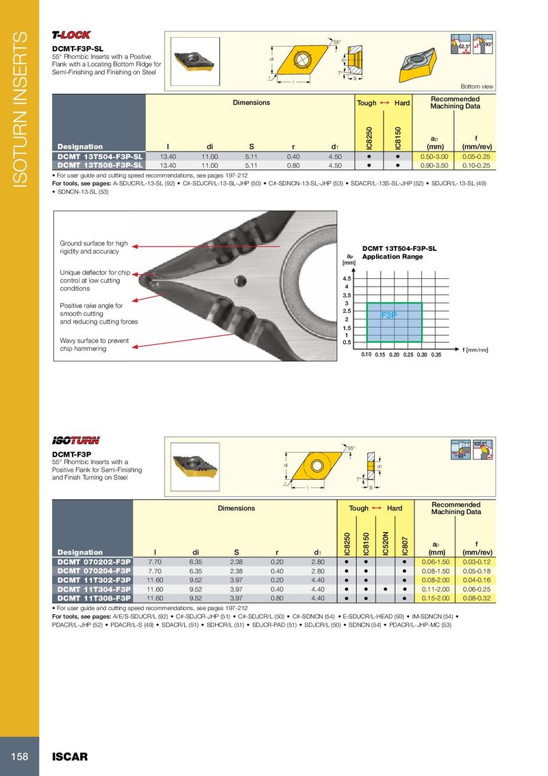
55° 62.5° 93° DCMT-F3P-SL 55° Rhombic Inserts with a Positive di d1 Flank with a Locating Bottom Ridge for Semi-Finishing and Finishing on Steel 7° r S l Bottom view Recommended Dimensions Tough 1 Hard Machining Data a p f Designation l di S r d 1 IC8250 IC8150 (mm) (mm/rev) DCMT 13T504-F3P-SL 13.40 11.00 5.11 0.40 4.50 • • 0.50-3.00 0.05-0.25 DCMT 13T508-F3P-SL 13.40 11.00 5.11 0.80 4.50 • • 0.90-3.50 0.10-0.25 • For user guide and cutting speed recommendations, see pages 197-212 ISOTURN INSERTS For tools, see pages: A-SDUCR/L-13-SL (92) • C#-SDJCR/L-13-SL-JHP (50) • C#-SDNCN-13-SL-JHP (53) • SDACR/L-13S-SL-JHP (52) • SDJCR/L-13-SL (49) • SDNCN-13-SL (53) Ground surface for high rigidity and accuracy DCMT 13T504-F3P-SL ap Application Range [mm] Unique deflector for chip control at low cutting 4.5 conditions 4 3.5 Positive rake angle for 3 smooth cutting 2.5 F3P and reducing cutting forces 2 1.5 1 Wavy surface to prevent 0.5 chip hammering f [mm rev] 0.10 0.15 0.20 0.25 0.30 0.35 107.5° 55° DCMT-F3P 93º 55° Rhombic Inserts with a di d 1 Positive Flank for Semi-Finishing and Finish Turning on Steel 7° r l S Recommended Dimensions Tough 1 Hard Machining Data a p f Designation l di S r d 1 IC8250 IC8150 IC520N IC807 (mm) (mm/rev) DCMT 070202-F3P 7.70 6.35 2.38 0.20 2.80 • • • 0.06-1.50 0.03-0.12 DCMT 070204-F3P 7.70 6.35 2.38 0.40 2.80 • • • 0.08-1.50 0.05-0.18 DCMT 11T302-F3P 11.60 9.52 3.97 0.20 4.40 • • • 0.08-2.00 0.04-0.16 DCMT 11T304-F3P 11.60 9.52 3.97 0.40 4.40 • • • • 0.11-2.00 0.06-0.25 DCMT 11T308-F3P 11.60 9.52 3.97 0.80 4.40 • • • 0.15-2.00 0.08-0.32 • For user guide and cutting speed recommendations, see pages 197-212 For tools, see pages: A/E/S-SDUCR/L (92) • C#-SDJCR-JHP (51) • C#-SDJCR/L (50) • C#-SDNCN (54) • E-SDUCR/L-HEAD (93) • IM-SDNCN (54) • PDACR/L-JHP (52) • PDACR/L-S (49) • SDACR/L (51) • SDHCR/L (51) • SDJCR-PAD (51) • SDJCR/L (50) • SDNCN (54) • PDACR/L-JHP-MC (53) 158 ISCAR