Каталог Iscar сверла ружейные и для глубокого сверления 2022 - страница 119
Навигация
 Каталог Iscar новые продукты 2018
 Каталог Iscar полирующие фрезы
 Каталог Iscar инструмент для фрезерования
 Каталог Iscar инструмент для нарезания резьбы
 Каталог Iscar токарные державки ISO 2022
 Фрезерные инструменты Iscar 2026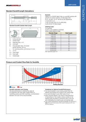
Standard Gundrill Length Calculations
H D
N W B F LA
Ls L Standard Gundrill Carbide Head Length H
D
| D= | Cutting diameter |
| H= | Carbide length |
| N= | Regrinding area = H-D |
| W= | Hole depth |
| B= | Chip evacuation area = For typical |
| gundrill machines, 250 mm | |
| = | For machining centers, 2xD (minimum 15 mm) |
| F= | 10 mm. |
| LA = Driver length | |
| LS = Flute length | |
| L= | Overall length |
Example Drilling of a ø10x500 depth hole on a gundrill machine with ø25x70 mm driver code No. 57 (See page 302) D=10 W=500 LA=70 B=250 (or per experience) L=N+W+B+F+LA L=(35-10)+500+250+13+70=858 (OAL) Ls=N+W+B=770 (flute length) Ordering Code For example: D and Ls are available as standard STGD-10000-0858-57-IC08 Diameter Range Head Length
| 2.50-3.80 | 20 |
| 3.80-4.05 | 23 |
| 4.05-5.05 | 25 |
| 5.05-6.55 | 30 |
| 6.55-11.05 | 35 |
| 11.05-18.35 | 40 |
| 18.35-21.35 | 45 |
| 21.35-23.35 | 50 |
| 23.35-26.35 | 55 |
| 26.35-32.00 | 65 |
Note: regrindable length=H-D
Pressure and Coolant Flow Rate for Gundrills
Bar L/min 120 120
| 110 | Q 110 | |
| 100 | L/D>100 | 100 |
| P | ||
| 90 | 90 | |
| 80 | 80 | |
| 70 | L/D<100 | 70 |
| 60 | 60 | |
| 50 | 50 | |
| 40 | 40 | |
| 30 | L/D>100 | 30 |
| 20 | L/D<100 | 20 |
| 10 | 10 |
Ø 2 4 6 8 10 12 14 16 18 20 22 24 26 28 30 32 40 mm
Drilling Diameter Q l/min P bar Gundrill Lubrication and Cooling Guidelines for Optimal Gundrill Performance The best performance is obtained by using oil. It is recommended to use a strong coolant flow for
On equipment that uses water-soluble fluids (i.e. efficient chip flushing and cooling of the cutting edge machining centers and CNC machines), a concentration It is recommended to use a filter under 20 µm between 10% and 15% is recommended. Note: Improper filtration may result in interrupted flow of lubricating oil. This creates a sticky surface on the bearing pads and leads to premature wear of the tool and overloading the coolant pump and spindle seals
- The coolant temperature should be between 20 and 22º C. Note: Above 50º C the viscosity of the coolant is reduced by 50% and becomes ineffective.