Каталог Iscar обработка канавок 2022 - страница 91
Навигация
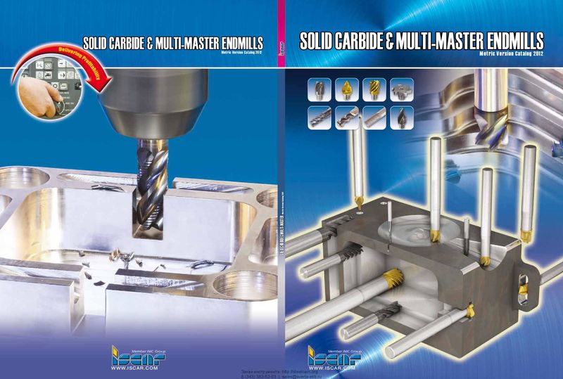 Каталог Iscar монолитные концевые фрезы и система multi-master
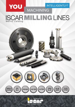 Фрезерные инструменты Iscar 2026
 Каталог Iscar сверла ружейные и для глубокого сверления 2022
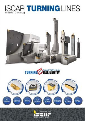 Каталог Iscar токарные державки ISO 2022
 Каталог Iscar инструмент для обработки алюминиевых колёс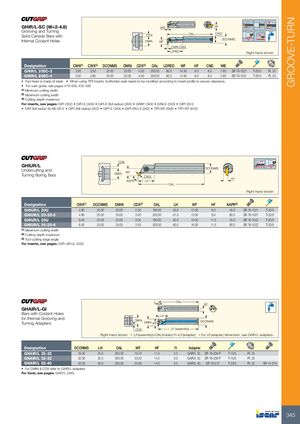
| GHIR/L-SC (W=2-4.8) Grooving and Turning Solid Carbide Bars with Internal Coolant Holes | D | CDX MIN | WB WF CW LDR | N-CWX O ED | AL | H | CND DCO F | NMS Righ | t-hand s | hown | ||||
| Designation | CWN(1) | CWX(2) | DCONMS | DMIN | CDX(3) | OAL | LDRED | WF | HF | CND | WB | |||
| GHIR/L 20SC-3 | 2.00 | 3.50 | 20.00 | 20.00 | 4.50 | 200.00 | 60.0 | 14.50 | 9.0 | 8.5 | 1.60 | SR 76-1021 | T-20/5 | PL 20 |
| GHIR/L 20SC-4 | 3.00 | 4.80 | 20.00 | 20.00 | 4.50 | 200.00 | 60.0 | 14.50 | 9.0 | 8.5 | 2.60 | SR 76-1021 | T-20/5 | PL 20 |
- Tool head is made of steel.
- When using TIPI inserts, toolholder seat needs to be modified according to insert profile to ensure clearance.
- For user guide, see pages 419-428, 432-436
(1) Minimum cutting width (2) Maximum cutting width (3) Cutting depth maximum
For inserts, see pages: GIFI (352) GIFI-E (349) GIFI-E (full radius) (350) GIMIY (349) GINI-E (350) GIPI (351)
- GIPI (full radius W<M) (351)
- GIPI (full radius) (352)
- GIPI-E (349)
- GIPI-RX/LX (352)
- TIPI-MT (648)
- TIPI-WT (642)
| GHIUR/L Undercutting and Turning Boring Bars | CDX DMIN | WF L C KAPR | H WX | OAL | DCONMS | HF | |||||
| Right-han | d shown | ||||||||||
| Designation | CWX(1) | DCONMS | DMIN | CDX(2) | OAL | LH | WF | HF | KAPR(3) | ||
| GHIUR/L 20U | 4.80 | 20.00 | 20.00 | 2.50 | 160.00 | 40.0 | 12.50 | 9.0 | 45.0 | SR 76-1021 | T-20/5 |
| GHIUR/L 20-20-5 | 4.80 | 20.00 | 20.00 | 3.00 | 200.00 | 51.0 | 13.00 | 9.0 | 60.0 | SR 76-1021 | T-20/5 |
| GHIUR/L 25U | 6.40 | 25.00 | 25.00 | 3.00 | 160.00 | 50.0 | 15.50 | 11.5 | 45.0 | SR 76-1022 | T-20/5 |
| GHIUR/L 25-25-6 | 6.40 | 25.00 | 25.00 | 3.50 | 200.00 | 60.0 | 16.00 | 11.5 | 60.0 | SR 76-1022 | T-20/5 |
(1) Maximum cutting width (2) Cutting depth maximum (3) Tool cutting edge angle
For inserts, see pages: GIPI-UR/UL (353)
| f1 | OAL | HF | |||||||||
| GHAIR/L-GI Bars with Coolant Holes for Internal Grooving and Turning Adapters | DMIN CDX | DMIN WF LH | LF (asse | mbly) | DCONMS | ||||||
| Right- | hand shown | •LF(ass | embly)=OAL(hol | der)-f1+LF | (adapter) | •For LF(adapter) | dimension, | see GAIR/L | adapters. | ||
| Designation | DCONMS | LH | OAL | WF | HF | f1 | Adapte | r | |||
| GHAIR/L 25-32 | 25.00 | 25.0 | 200.00 | 19.70 | 11.5 | 3.0 | GAIR/L 3 | 2.. SR 16-236 P | T-15/5 | PL 25 | |
| GHAIR/L 32-32 | 32.00 | 32.0 | 200.00 | 23.20 | 14.5 | 3.0 | GAIR/L 3 | 2.. SR 16-236 P | T-15/5 | PL 32 | |
| GHAIR/L 32-40 | 32.00 | 40.0 | 200.00 | 24.00 | 14.5 | 3.0 | GAIR/L 4 | 0.. SR 16-212 | T-20/5 | PL 32 | SR 14-519 |
- For DMIN & CDX refer to GAIR/L adapters
For tools, see pages: GAIR/L (346)