Каталог Iscar обработка канавок 2022 - страница 30
Навигация
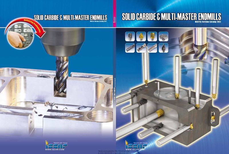 Каталог Iscar монолитные концевые фрезы и система multi-master
 Фрезерные инструменты Iscar 2026
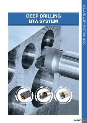 Каталог Iscar сверла ружейные и для глубокого сверления 2022
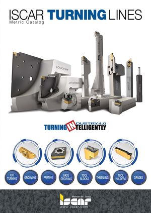 Каталог Iscar токарные державки ISO 2022
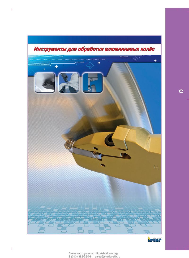 Каталог Iscar инструмент для обработки алюминиевых колёс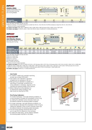
| CGHR/L-P8DG | OHX CW | |
| Double-Ended Heavy Duty | ||
| Self-Clamped Grooving | HF | H |
| and Turning Blades | ||
| WB | ||
| OAL | ||
| CGHR | CGHL |
| Designation | CW | OHX(1) | WB | HF | H | OAL | |
| CGHR/L 32-P8DG | 8.00 | 40.0 | 6.80 | 24.8 | 32.0 | 150.00 | EDG 44A* |
- For user guide, see pages 419-428, 432-436
(1) Minimum overhang If CUTDIA (workpiece) is smaller than 200 mm, then CDX=48; if CUTDIA (workpiece) is larger than 200 mm, then CDX=43
- Optional, should be ordered separately
For inserts, see pages: GIMF (288) GIMM 8CC (583) GIMY (288) GIMY (full radius) (290) GIMY-F (291) GIPY (300)
For holders, see pages: C#-TBK-R/L (623) HSK A-WH-TBK-R/L (632) SGTBK (617) SGTBU/SGTBN (616)
TGFHM CGHNM OAL OHX CDX
| Anti-Vibration Blades | H | HF | |
| Anti-Vibration Blades for Deep | |||
| Grooving and Turning | |||
| WB | |||
| CWN-CWX |
| Designation | CWN(1) | CWX(2) | OHX(3) | CDX(4) | WB | HF | H | OAL | Insert | |||
| CGHNM 53-6DG-AV | 5. 50 | 6.40 | 100.0 | 93.00 | 5.20 | 45.0 | 52.6 | 235.00 GIMF/N/T/Y 6 GIM 6 SGCU 341 OR 30X3 NBR EDG 44A* | T-6/5 SGC 340 | |||
| TGFHM 53K-8-AV | 7.70 | 9.00 | 100.0 | 93.00 | 7.40 | 45.0 | 52.6 | 235.00 | TAG/TAGB 8 | SGCU 341 OR 30X3 NBR ETG 8-12* | T-6/5 SGC 340 | |
| CGHNM 53-P8-AV | 8.00 | 8.00 | 100.0 | 93.00 (5) | 7.40 | 45.0 | 52.6 | 235.00 | GIMY/F/MM 8 | SGCU 341 OR 30X3 NBR | T-6/5 SGC 340 HW 4.0 |
- For user guide, see pages 419-428, 432-436
(1) Minimum cutting width (2) Maximum cutting width (3) Maximum overhang (4) Cutting depth maximum (5) For CUTDIA<200 CDX=98
- Optional, should be ordered separately
For inserts, see pages: GIA-K (W=3-6) (298) GIF (297) GIF (full radius) (298) GIF-E (W=4-6 full radius) (294) GIF-E (W=4-6) (292) GIM-C (521) GIMF (288)
- GIMM 8CC (583)
- GIMN (289)
- GIMT (287)
- GIMY (288)
- GIMY (full radius) (290)
- GIMY-F (291)
- GIP (297)
- GIP-E (293)
- GIPA (full radius W=3-6) (301)
- GIPA (W=3-6) (300)
- GIPY (300)
- GITM (299)
- GITM (full radius) (299)
- TAG N-C/W/M (506)
- TAGB/TAGBA (333)
For holders, see pages: SGTBK (617) SGTBU/SGTBN (616)
User Guide
- To maintain a stable and controlled machining process use constant RPM (G97).
- Each blade is pre-calibrated in laboratory conditions for an overhang of 100 mm.
- Although the pre-calibration is suitable for a wide range of overhangs, sometimes finetuning calibration is necessary, depends on the overhang and clamping rigidity of the machine.
- Before making fine tuning calibration try to optimize the cutting conditions. First step should be reducing the RPM. Damping
plates
Fine-Tuning Calibration
For shorter overhangs / more rigid clamping conditions, it
is recommended to increase the compression of the O-ring Distance
by rotating the calibration screw clockwise (make sure between
the distance between the damping plates increases). plates
Calibration
- For longer overhangs / less rigid clamping conditions, it is screw recommended to decrease the compression of the O-ring by O-Ring rotating the calibration screw counter clockwise (make sure the distance between the damping plates decreases).
- The fine-tuning resolution should be about a halfturn for each 30 mm difference in the overhang.
- To restore the initial setup, use the distance between the damping plates imprinted on the blade.