Каталог Iscar обработка канавок 2022 - страница 194
Навигация
 Каталог Iscar монолитные концевые фрезы и система multi-master
 Каталог Iscar сверла ружейные и для глубокого сверления 2022
 Каталог Iscar токарные державки ISO 2022
 Каталог Iscar инструмент для обработки алюминиевых колёс
 Каталог Iscar инструментальная оснастка 2022
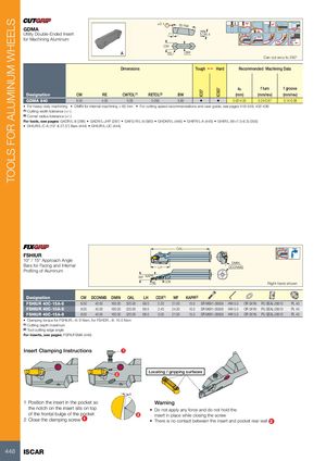
TOOLS FOR ALUMINUM WHEELS IC07 IC507 ±0.1 30 Ref. GDMA Utility Double-Ended Insert 7° 6.4 for Machining Aluminum CW RE BW Can cut arcs to 250° Dimensions Tough 1 Hard Recommended Machining Data ap f turn f groove Designation CW RE CWTOL(1) RETOL(2) BW (mm) (mm/rev) (mm/rev) GDMA 840 8.00 4.00 0.05 0.050 5.60 • • 0.00-4.00 0.24-0.67 0.14-0.38 • For heavy-duty machining • DMIN for internal machining = 65 mm • For cutting speed recommendations and user guide, see pages 419-428, 432-436 (1) Cutting width tolerance (+/-) (2) Corner radius tolerance (+/-) For tools, see pages: GADR/L-8 (286) • GADR/L-JHP (287) • GAFG-R/L-8 (580) • GHDKR/L (446) • GHIFR/L-A (445) • GHIR/L (W=7.0-8.3) (355) • GHIUR/L-C-A (15° & 27.5°) Bars (444) • GHIUR/L-UC (444) OAL FSHIUR 10° / 15° Approach Angle Bars for Facing and Internal DMINLHDCONMS Profiling of Aluminum WF KAPR RE CDX Right-hand shown Designation CW DCONMS DMIN OAL LH CDX(1) WF KAPR(2) FSHIUR 40C-15A-6 6.00 40.00 160.00 320.00 68.0 2.20 21.00 15.0 SR M6X1-28509 HW 5.0 OR 5X1N PU SEAL-28510 PL 40 FSHIUR 40C-10A-8 8.00 40.00 160.00 320.00 68.0 2.40 24.30 10.0 SR M6X1-28509 HW 5.0 OR 5X1N PU SEAL-28510 PL 40 FSHIUR 40C-15A-8 8.00 40.00 160.00 320.00 68.0 3.00 21.00 15.0 SR M6X1-28509 HW 5.0 OR 5X1N PU SEAL-28510 PL 40 • Clamping torque for FSHIUR..-6: 9 Nxm, for FSHDR..-8: 10.5 Nxm (1) Cutting depth maximum (2) Tool cutting edge angle For inserts, see pages: FSPA/FSMA (449) Insert Clamping Instructions 1 2 Locating / gripping surfaces 1 Position the insert in the pocket so Warning the notch on the insert sits on top • Do not apply any force and do not hold the of the frontal bulge of the pocket 2 insert in place while closing the screw 2 Close the clamping screw 1 • There is no contact between the insert and pocket rear wall 2 448 ISCAR