Каталог Iscar дисковые фрезы и фрезерные пластины 2022 - страница 65
Навигация
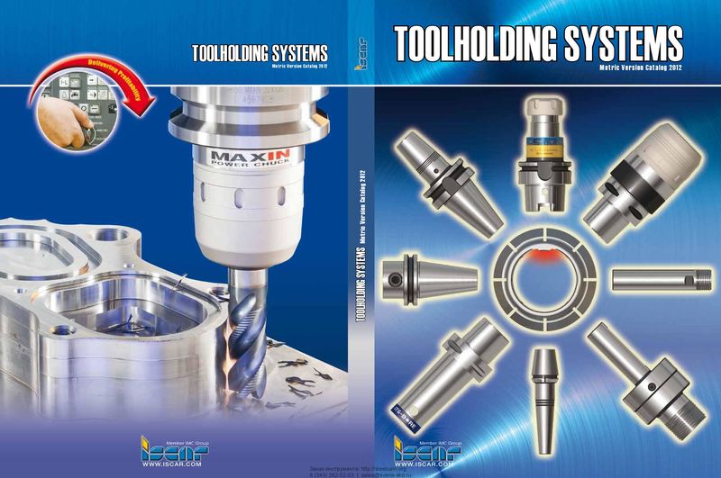 Каталог Iscar крепление инструмента
 Каталог Iscar инструмент для обработки отверстий
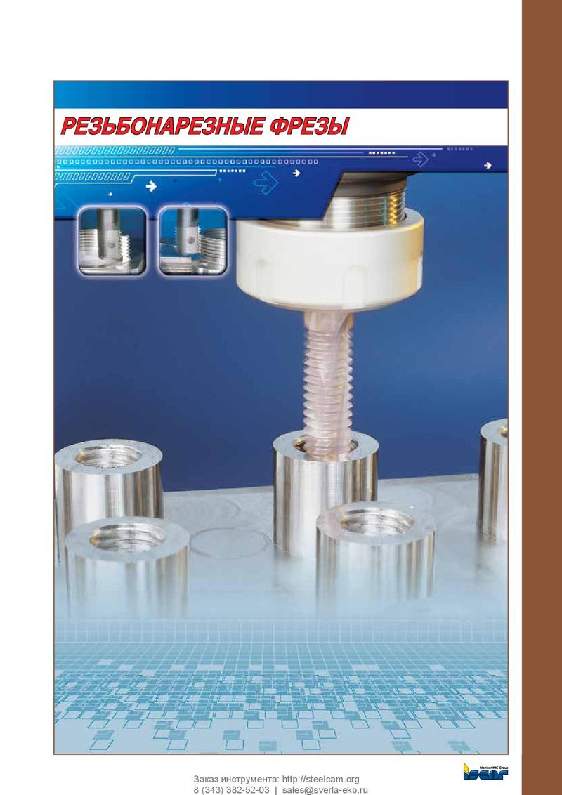 Каталог Iscar резьбонарезные фрезы
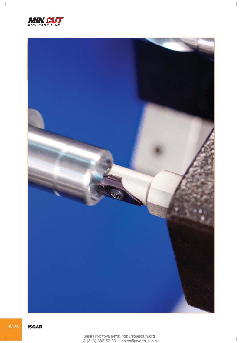 Каталог Iscar инструмента для сверления
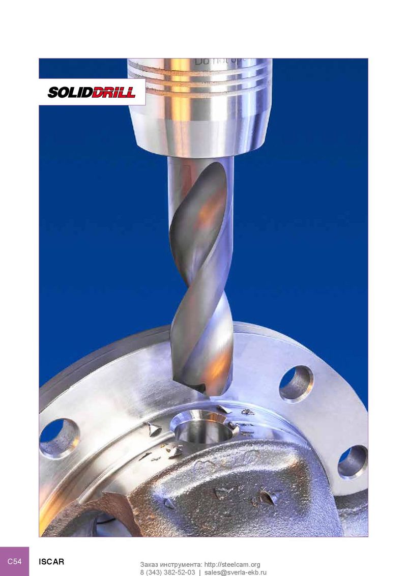 Каталог Iscar решения для глубокого сверления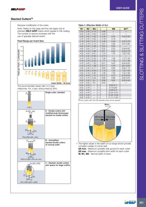
Stacked Cutters(1)
Requires modification of the cutter. Table 1: Effective Width of Cut
| W1 | W2 | WA | WB | Wc(1) | ||
| 2.40 | 2.40 | 4.14 | - | 4.48 | — | — |
| 3.00 | 2.40 | 4.53 | - | 5.04 | — | — |
| 3.00 | 3.00 | 4.92 | - | 5.39 | 5.40 | 5.43-5.60 |
| 3.18 | 2.40 | 4.62 | - | 5.18 | 5.19 | — |
| 3.18 | 3.00 | 5.01 | - | 5.48 | 5.49 | 5.52-5.76 |
| 3.18 | 3.18 | 5.10 | - | 5.57 | 5.58 | 5.61-5.92 |
| 4.05 | 2.40 | 5.38 | - | 6.02 | 6.03 | — |
| 4.05 | 3.00 | 5.77 | - | 6.32 | 6.33 | 6.36-6.62 |
| 4.05 | 3.18 | 5.86 | - | 6.41 | 6.42 | 6.45-6.78 |
| 4.05 | 4.05 | 6.61 | - | 7.24 | 7.25 | 7.28-7.63 |
| 4.78 | 2.40 | 6.06 | - | 6.74 | — | — |
| 4.78 | 3.00 | 6.45 | - | 7.08 | 7.09 | 7.12-7.30 |
| 4.78 | 3.18 | 6.54 | - | 7.17 | 7.18 | 7.21-7.46 |
| 4.78 | 4.05 | 7.30 | - | 8.01 | 8.02 | 8.05-8.32 |
| 4.78 | 4.78 | 7.98 | - | 8.77 | 8.78 | 8.81-9.00 |
| 5.00 | 2.40 | 6.17 | - | 6.89 | 6.90 | 6.93-7.12 |
| 5.00 | 3.00 | 6.56 | - | 7.19 | 7.20 | 7.23-7.52 |
| 5.00 | 3.18 | 6.65 | - | 7.28 | 7.29 | 7.32-7.68 |
| 5.00 | 4.05 | 7.41 | - | 8.12 | 8.13 | 8.16-8.54 |
| 5.00 | 4.78 | 8.09 | - | 8.88 | 8.89 | 8.92-9.22 |
| 5.00 | 5.00 | 8.2 | - | 8.99 | 9.00 | 9.03-9.44 |
| 5.20 | 5.00 | 8.3 | - | 8.42 | — | — |
| 6.35 | 3.00 | — | — | 8.64-8.71 | ||
| 6.35 | 3.18 | — | — | 8.73-8.87 | ||
| 6.35 | 4.05 | — | — | 9.56-9.72 | ||
| 6.35 | 4.78 | — | — | 10.33-10.41 | ||
| 6.35 | 5.00 | — | — | 10.44-10.63 | ||
| 6.35 | 6.35 | — | — | 11.71-11.81 | ||
| (1)Only c | utters wit | h 160-25 | 0 di | ameter siz | es can be stacked | . |
0.25
chipformer. For J-type, reduce feed by 30%.
W A=ΔA ΔA 1+ 2
A1 A 2
A - Double cutters with modified body thicknesses stacked for smaller widths
Shim...
∆S max ∆S max
1 2
W1 W 2 WA WA=WB-(ΔA1+ΔA2) A 1 A2
W1 W 2 WB WB=0.5x(W1+W2+A1+A2) S=ΔS1+ΔS2
B - Unmodified, stacked double cutters of nominal width
C - Stacked, double cutters with spacer for larger widths
1 The higher values in the width-of-cut range shown provide complete overlap of corner radii. ∆A max - Maximum possible side ground for each cutter ∆S max - Maximum possible shim width for each cutter W, W1, W2 - Normal width of insert
W1 W2 WC WC=WB+(ΔS1+ΔS2)